
Level sensor for conductive liquids

a technology of conductive liquid and level sensor, which is applied in the direction of indirect fuel cells, instruments, process and machine control, etc., can solve the problems of inaccurate measurement, only measuring whether, and conventional resistive-type sensors

Inactive Publication Date: 2012-07-31
IMERGY POWER SYST
View PDF124 Cites 12 Cited by
  • Summary
  • Abstract
  • Description
  • Claims
  • Application Information

AI Technical Summary

Benefits of technology

"The present invention is about a level sensor for measuring the level of a conductive liquid in a holding tank. The sensor has two electrodes that are placed in the tank and connected to sensor leads. The resistance between the electrodes is measured using the sensor leads, which is used to determine the level of the liquid in the tank. This invention provides a simple and effective way to measure the level of a conductive liquid in a holding tank."

Problems solved by technology

However, conventional resistive-type sensors can only measure whether or not an electrolyte is at a predetermined level.
Moreover, resistive-type sensors typically use highly metallic electrodes, which quickly corrode in the corrosive electrolyte, resulting over time, in inaccurate measurements.
Furthermore, capacitive and resistive electrolyte level sensors typically are only capable of measuring a level, such that flow battery systems require additional sensors for determining other parameters such as the temperature of an electrolyte.

Method used


Image

  • Level sensor for conductive liquids
  • Level sensor for conductive liquids
  • Level sensor for conductive liquids

Examples


Embodiment Construction

[0022]In the following description, for the purposes of explanation, specific details are set forth in order to provide a thorough understanding of the embodiments of the invention. However, it will be apparent that the invention may be practiced without these specific details.

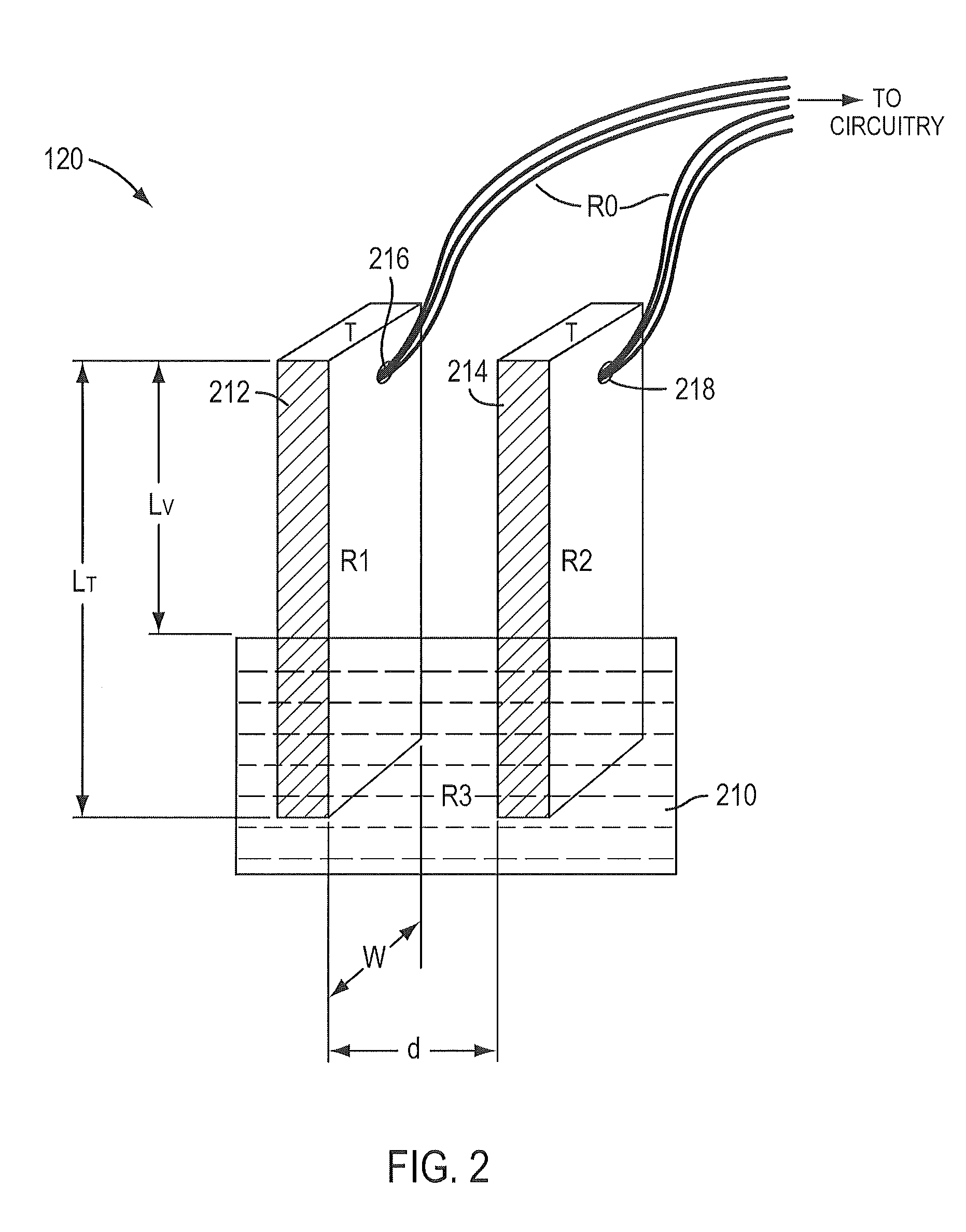
[0023]Some embodiments consistent with the present invention may provide a reliable way to measure a level of an electrolyte, or other conductive liquid, in a tank, without the introduction of any unwanted metals, dangerous electrical current, or other external materials or forces which affect the operation of the system. Some embodiments consistent with the present invention may also provide a location for a temperature sensor for measuring the temperature of an electrolyte or other conductive liquid.

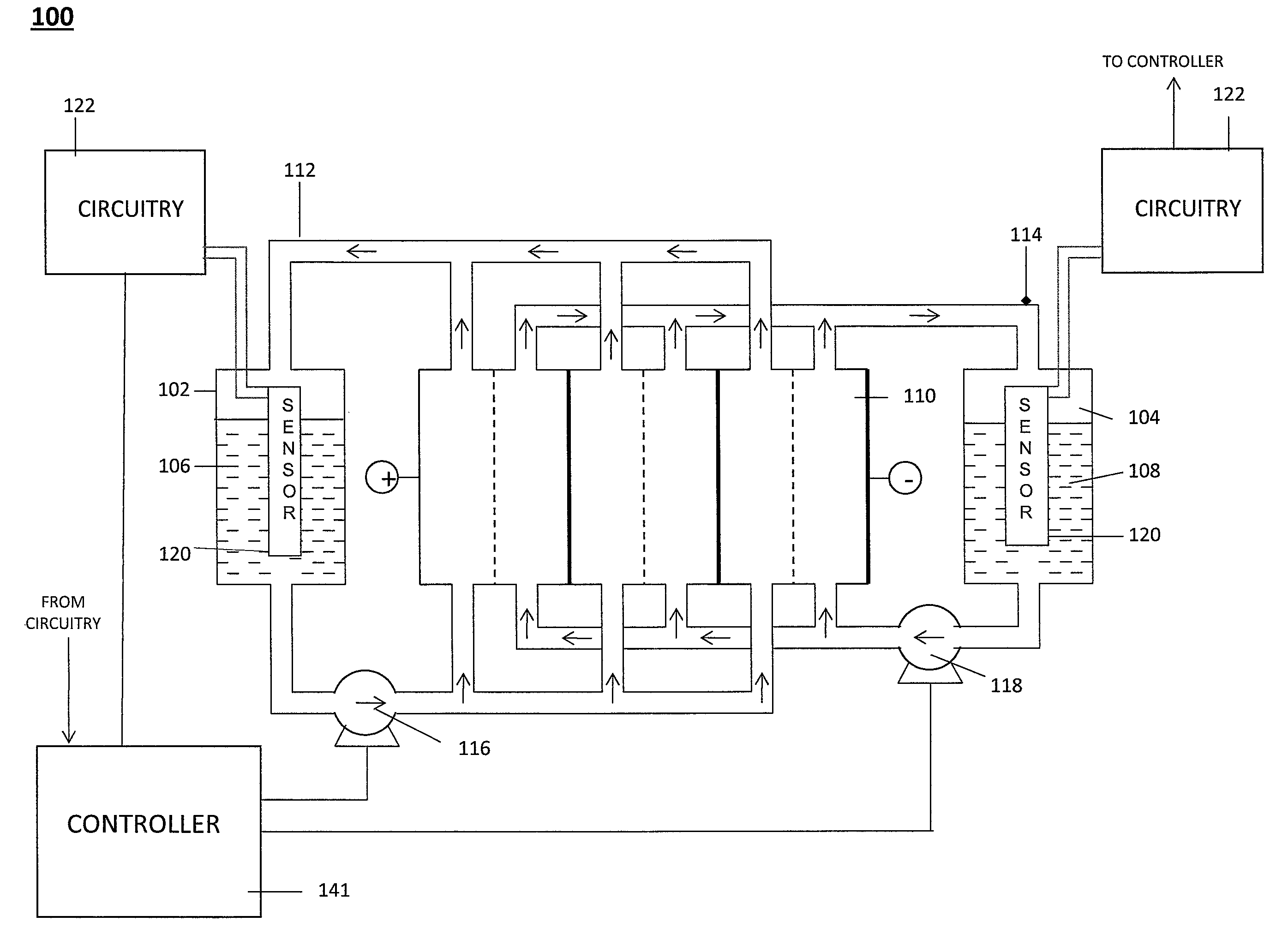
[0024]FIG. 1 illustrates a flow battery system 100 in accordance with aspects of the present invention. As shown in FIG. 1, flow battery system 100 includes storage tanks 102 and 104 for storing fluids 106 and 10...


PUM


Abstract

A sensor for measuring a level of a conductive liquid, is provided. The sensor includes at least two electrodes that can be positioned in a holding tank so as to be partially submerged in the conductive liquid, sensor leads coupled to the at least two electrodes, and circuitry and a controller for determining the properties of the electrolyte, the circuitry being coupled to the at least two electrodes via the sensor leads, and the controller being coupled to the circuitry. The sensor may be used as an electrolyte level sensor in a flow battery system.

Description

CROSS-REFERENCE TO RELATED APPLICATIONS[0001]The present application claims benefit under 35 U.S.C. §119(e) of U.S. Provisional Application No. 61 / 104,600 filed on Oct. 10, 2008, entitled “Sensor For Measuring Fluid Level,” the content of which is hereby incorporated by reference in its entirety.BACKGROUND[0002]1. Technical Field[0003]Embodiments consistent with the present invention are related to conductive liquid sensors. In particular, some embodiments consistent with the present invention are related to measuring a level of an electrolyte in a holding tank of a flow battery system.[0004]2. Discussion of Related Art[0005]Fluids in a system often have important dynamic properties which are important to the overall operation of a system. Accordingly, sensors have been developed which measure these dynamic properties to monitor the state of the system. One such system is a reduction-oxidation (redox) flow battery system.[0006]A redox flow battery is an electrochemical storage devic...

Claims


Application Information

Patent Timeline
Patent Type & Authority Patents(United States)
IPC IPC(8): G01F23/26G01F23/24
CPCG01F23/0076G01F23/24H01M8/188H01M8/20Y02E60/528Y02E60/50G01F23/804
Inventor SAHU, SAROJ KUMARCONWAY, BRUCE
Owner IMERGY POWER SYST
Learn More