
Intelligent mode switching in communication networks

a communication network and intelligent mode technology, applied in the field of intelligent mode switching in communication networks, can solve the problems of limited usefulness under other conditions, limited effective use, and less efficient use of available spectrum, and achieve the effect of maximizing the overall system capacity and facilitating on-the-go switching

Inactive Publication Date: 2012-07-24
ADAPTIX
View PDF48 Cites 15 Cited by
  • Summary
  • Abstract
  • Description
  • Claims
  • Application Information

AI Technical Summary

Benefits of technology

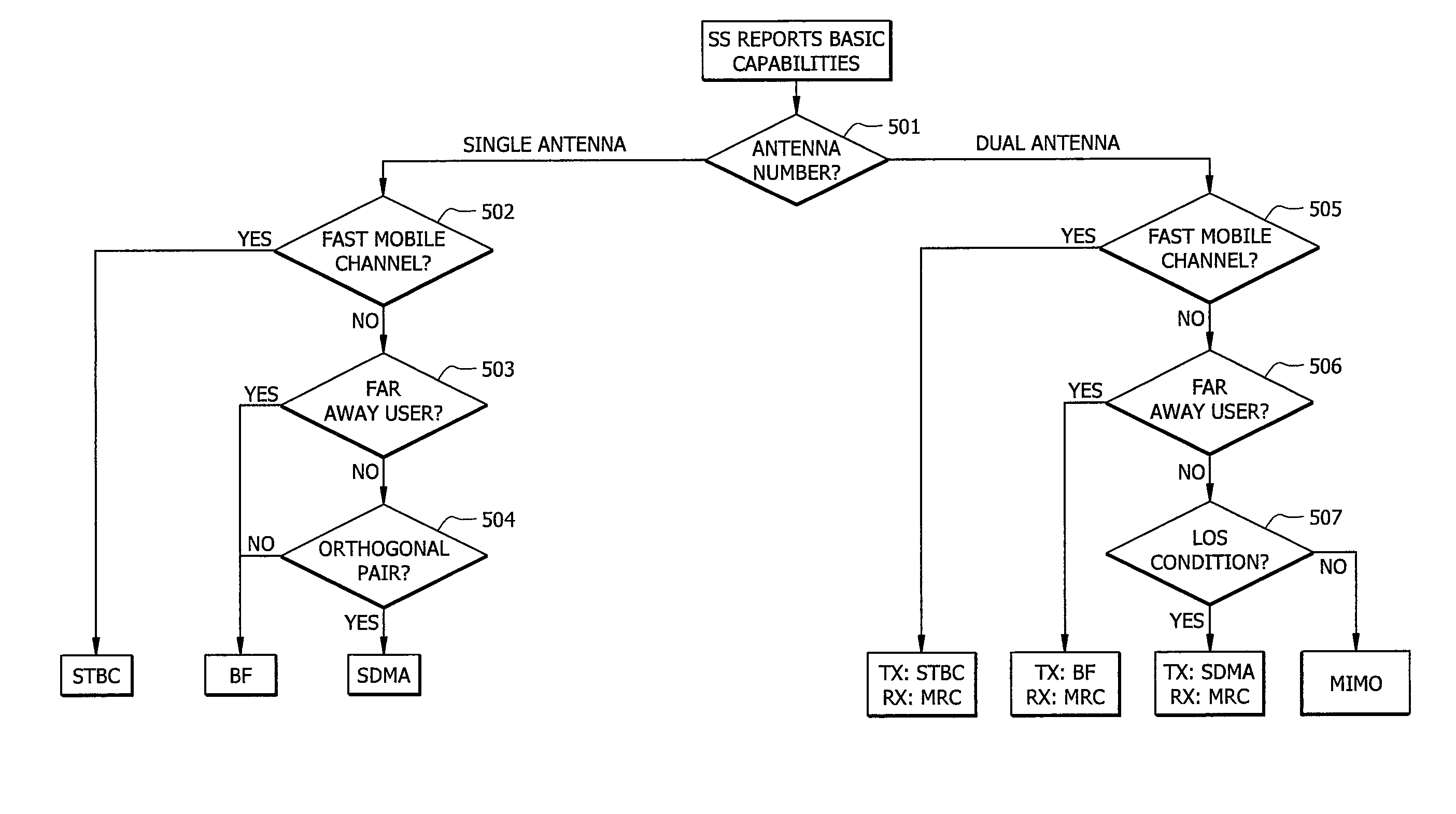
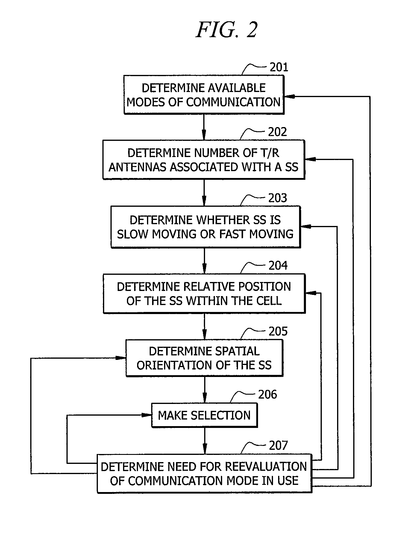
The patent text describes a need for an intelligent method to switch between different modes of communication in a communication network. This method should be applicable to a wide range of networks and based on factors like the number of antennas and communication channel conditions. The ultimate goal is to ensure reliable link and maximize overall system capacity while optimizing communication modes for individual users. The patent text also describes a preferred embodiment of the invention that involves determining the mobility, position, and orthogonality of a subscriber station to select the most suitable communication mode for link reliability and network performance.

Problems solved by technology

Each of these multiple antenna array communication modes is advantageously used under certain conditions, but are of only limited usefulness under other conditions.
For example, SDMA schemes provide good coverage and efficient use of available spectrum, but are limited to effective use only with non-moving or slow-moving SSs.
An STBC scheme is best used for fast-moving, dynamic SSs, but provides less efficient use of available spectrum.
More often than not, simply employing a single mode of communication for communication is not practical because any given mode is not versatile enough to be useful across a sufficiently wide range of conditions.
Nevertheless, these schemes are somewhat limited in that they only provide switching between, at best, two modes.
Also, such systems are limited because they typically consider only SS position when deciding to switch between communication modes.
While some of these systems are touted as being operable to switch between multiple antenna modes; at best, these systems switch between only two modes and are limited to point-to-point communication.
Further, these systems do not optimize communication mode selection point-to-multiple-point in a multi-cell context.
Another communication mode, e.g., BF will not be available to that user because it has not been implemented in such an environment.
However, in no case has MIMO, for example, been additionally implemented in the same network.

Method used


Image

  • Intelligent mode switching in communication networks
  • Intelligent mode switching in communication networks
  • Intelligent mode switching in communication networks

Examples


Embodiment Construction

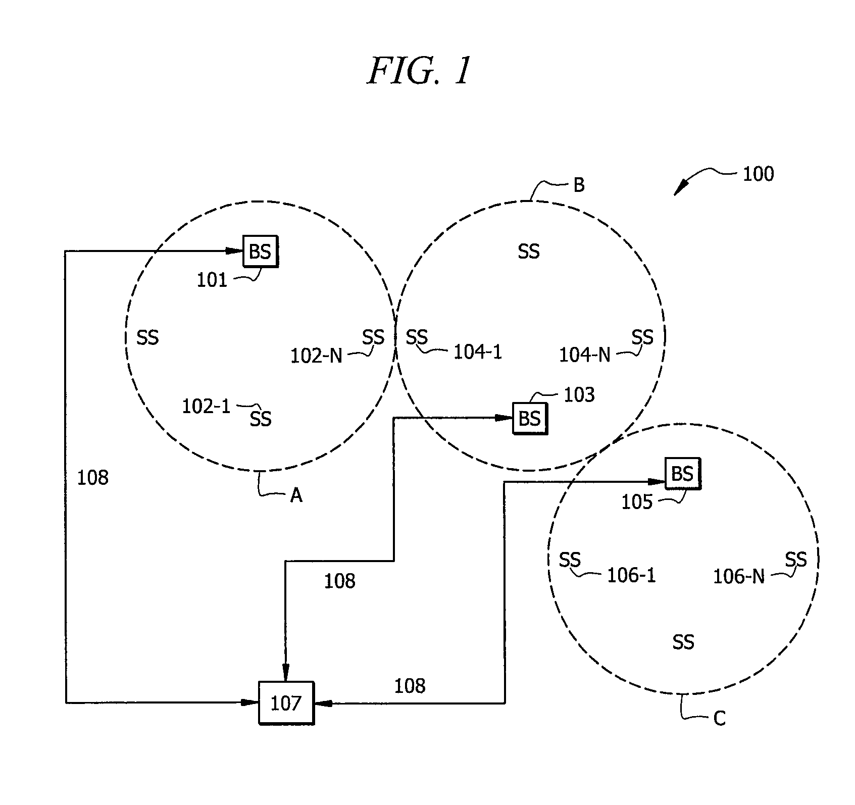
[0013]Referring to FIG. 1, communication system 100 is adapted to provide intelligent communication mode switching in the uplink (communications from the SS to the BS) and the downlink (communications from the BS to SS). System 100 can be generalized to most communication networks and includes network components as known in the art adapted to provide operation as described herein. BS 101 communicates with SS 102-1 through 102-N and vice versa in cell A, BS 103 communicates with SSs 104-1 though 104-N and vice versa in cell B, and BS 105 communicates with SSs 106-1 through 106-N and vice versa in cell C. Each of BS 101, 103, and 105 communicate on “backhaul” network 107 via communication means 108. Communication means 108 may comprise phone lines, RF communication components, and the like as known in the art.

[0014]As will be described in greater detail below, system 100 implements an intelligent methodology whereby an iterative process is executed to select, from a number of possibil...


PUM


Abstract

Systems and methods for intelligently switching between communication modes. An optimum communication mode is selected based upon determining the mobility of the subscriber station, the location of the subscriber station, and orthogonality of signals received from the subscriber station with respect to a signal of another subscriber station. Each determination may be continually or incrementally performed according to the passage of a time interval or upon observation of changes in relevant conditions.

Description

TECHNICAL FIELD[0001]The present invention generally relates to communication networks. In particular, the present invention relates to systems and methods for providing intelligent communication mode switching in the uplink and / or downlink for communication across a network.BACKGROUND OF THE INVENTION[0002]In communication networks, different schemes have been used to improve communication between a base station (BS) and subscriber station (SS) across the network. For example, some networks employ a single transmit antenna and single receive antenna at the BS and subscriber station SS. These systems may improve communication, i.e., increase SINR, by employing adaptive coding / modulation schemes, where the signal modulation scheme is adjusted to effectuate an increase in SINR. Other networks employ different antenna array modes, i.e., modes of communication, between a BS and a SS where each of the BS and SS have multiple antennas. Examples of these multiple antenna array communicatio...

Claims


Application Information

Patent Timeline
Patent Type & Authority Patents(United States)
IPC IPC(8): G01R31/08H04W4/00H04J3/16
CPCH04W72/046H04B7/0689H04L1/0006H04L1/0015H04L1/0643H04B7/0413H04B7/0617H04B7/0669H04B7/0857
Inventor XING, GUANBINSHEN, MANYUANSHAO, XUN
Owner ADAPTIX
Learn More