
Electronic control method for a planar inductive battery charging apparatus

a charging apparatus and electric control technology, applied in the direction of electric vehicles, dc-dc conversion, transportation and packaging, etc., can solve the problems of heat generation and power loss in the metallic table or conductive surface, and defeat the purpose of designing a thin charging platform

Active Publication Date: 2012-07-24
CITY UNIVERSITY OF HONG KONG
View PDF22 Cites 58 Cited by
  • Summary
  • Abstract
  • Description
  • Claims
  • Application Information

AI Technical Summary

Benefits of technology

The system effectively confines magnetic flux, reduces power loss, and meets EMC requirements by generating a controlled AC magnetic field that can charge multiple devices simultaneously while maintaining a slim design and cost-effectiveness.

Problems solved by technology

The increasing popularity of portable consumer electronic products such as mobile phones, MP3 players and PDAs has prompted new concerns on the huge variety and number of battery chargers that are required and which are costly, inconvenient and eventually lead to electronic waste problems.
However, these battery chargers do not use a planar structure and each charger is only able to charge one item of electronic equipment at a time.
A fundamental and inherent limitation of this type of battery charger is that this charging device must have a good electromagnetic flux guide to confine the flux along the lower surface.
Otherwise, if such a charging device is placed on a metallic table or a conductive surface, induced current will circulate in the metallic table or conductive surface, resulting in heat generation and power loss in the metallic table or conductive surface.
However, if the electromagnetic flux is large, a fairly thick layer of soft-magnetic material is needed, defeating the purpose of designing a “thin” charging platform and increasing the cost due to the large amount of soft magnetic material required.
In addition, the electromagnetic shielding effect of using one layer of soft magnetic material may not be sufficient for electromagnetic compatibility (EMC) requirements.
This results in the possibility of a slim design for the secondary module that can be embedded in the portable electronic load.

Method used


Image

  • Electronic control method for a planar inductive battery charging apparatus
  • Electronic control method for a planar inductive battery charging apparatus
  • Electronic control method for a planar inductive battery charging apparatus

Examples


Embodiment Construction

[0029]For planar battery charging systems, the use of a standard charging pad enables charging inductively a wide range of portable electronic products. In order provide such a pad, preferably several conditions are met:

(1) The windings of the charging pad that are excited are able to generate sufficient energy for charging these electronic products.

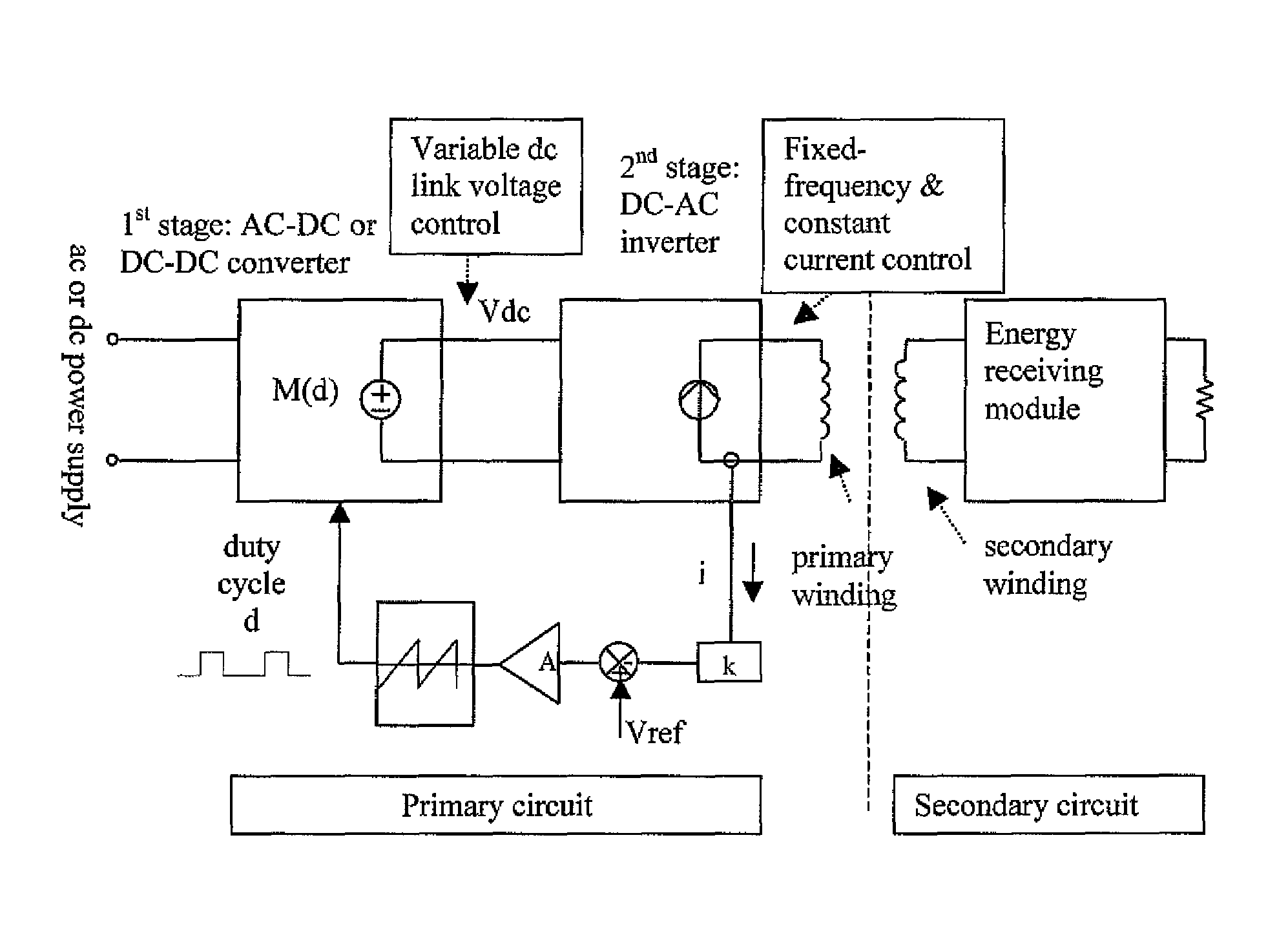
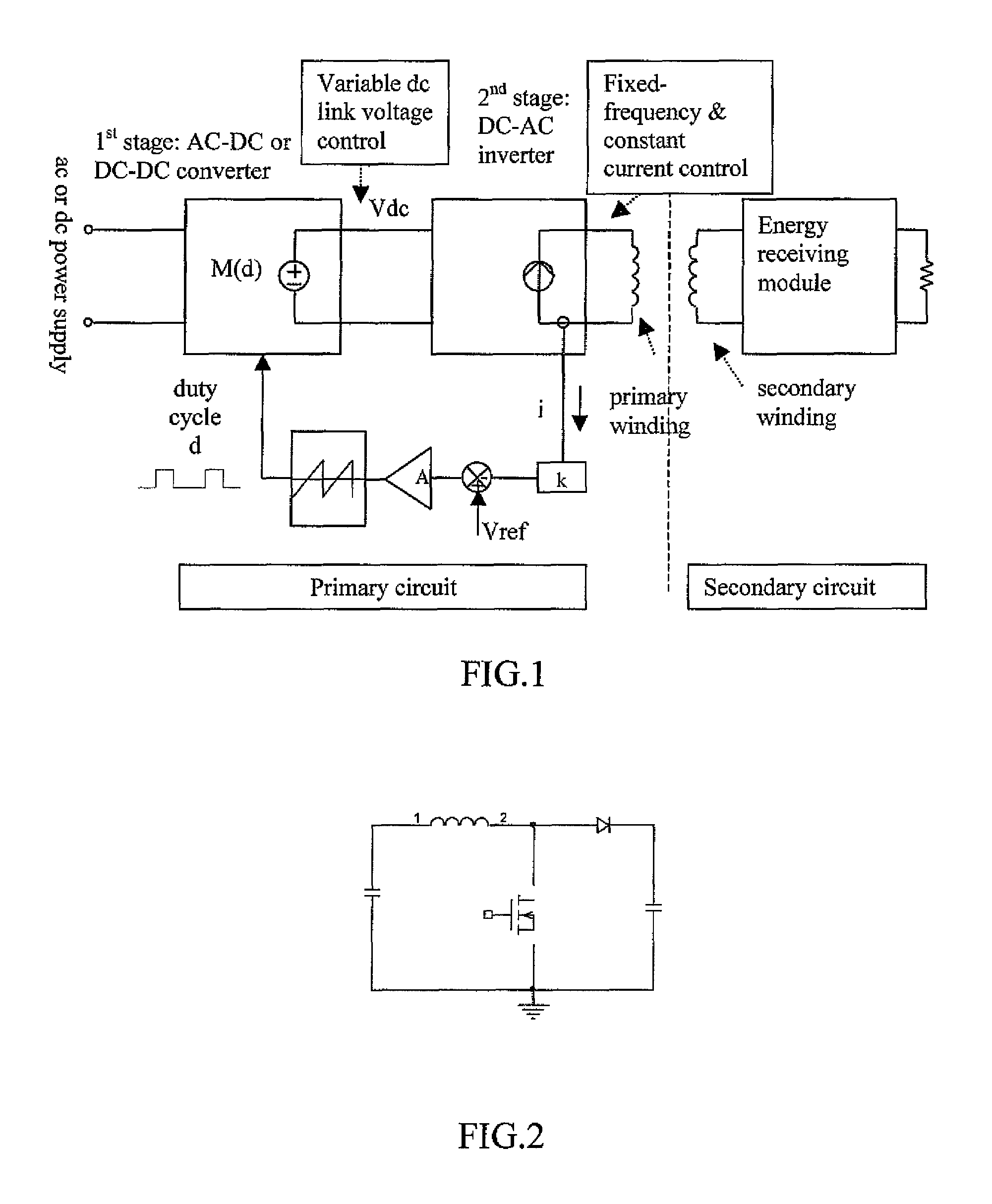
[0030](2) Since the inductive charging method relies on the near-field magnetic coupling of the charging pad (primary energy-transmitting circuit or simply primary circuit) and the energy-receiving module (secondary circuit) inside the electronic products, the charging pad should generate an AC magnetic flux of a controllable magnitude that can satisfy a wide range of portable electronic loads to be charged.

(3) Since a range of electronic loads may be charged on the same charging pad, there should be a standard operating frequency and a set of basic secondary circuit design features. In other words, the secondary circuits in a wide range...


PUM


Abstract

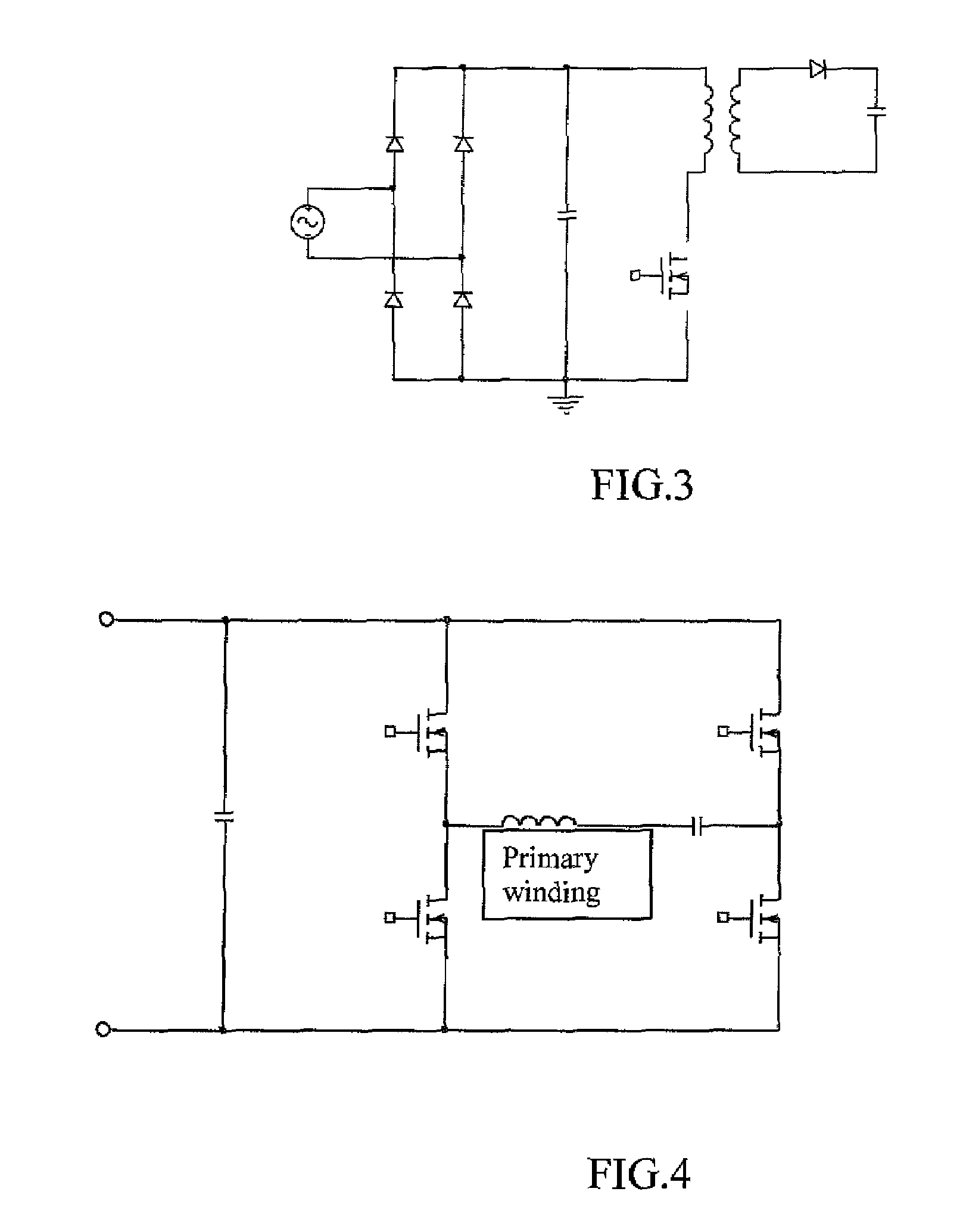
This invention provides an electronic control method for a planar inductive battery charging apparatus on which one or more electronic loads such as mobile phones, MP3 players etc can be placed and charged simultaneously. The power control circuit of the charging pad consists of two power conversion stages. Depending on the nature of the input power supply, the first power stage is an AC-DC power converter with variable output voltage control and a second stage is a DC-AC power inverter with constant current control. The combination of the two stages provides power control of the charging pad and generates AC magnetic flux of ideally constant magnitude over the charging areas within a group of primary windings that are excited.

Description

FIELD OF THE INVENTION[0001]This invention relates to methods and apparatus for the control of a planar battery charging apparatus.BACKGROUND OF THE INVENTION[0002]The increasing popularity of portable consumer electronic products such as mobile phones, MP3 players and PDAs has prompted new concerns on the huge variety and number of battery chargers that are required and which are costly, inconvenient and eventually lead to electronic waste problems. Inductive or wireless charging apparatus that can charge more than one electronic product have been proposed. Two different approaches to the generation of AC magnetic flux have been proposed, namely “horizontal flux” and “vertical flux” methods.[0003]Inductive electronic chargers with a direct connection have been developed for use with some types of portable electronic equipment such as electric toothbrushes. Inductive chargers have also been proposed in a number of documents such as U.S. Pat. No. 6,356,049, U.S. Pat. No. 6,301,128, U...

Claims


Application Information

Patent Timeline
Patent Type & Authority Patents(United States)
IPC IPC(8): H02J7/00H02J7/04
CPCH02J7/025H02J50/12H02J2207/20H02J7/00712H02M1/4258H02M7/4815H02M7/06H02M3/33571H02M3/01H02M3/33573H02M3/156H02M1/007H02M3/33507H02M1/44
Inventor HO, WING CHOILEE, CHI KWANHUI, RON SHU YUENCHUNG, SHU HUNG
Owner CITY UNIVERSITY OF HONG KONG
Learn More