
Automatic transmission and control method thereof

a technology of automatic transmission and control method, which is applied in the direction of instruments, mechanical devices, digital data processing details, etc., can solve the problems of deterioration of drivability, aggravated problems described above, and inability to restart the engine, so as to suppress the deterioration of drivability

Active Publication Date: 2012-07-17
JATCO LTD +1
View PDF9 Cites 1 Cited by
  • Summary
  • Abstract
  • Description
  • Claims
  • Application Information

AI Technical Summary

Benefits of technology

[0006]It is an object of this invention to specify a failed element by detecting the occurrence of a failure early, thereby suppressing deterioration of the drivability to a minimum.
[0008]According to this invention, a determination as to whether or not a failure has occurred in a friction element is made repeatedly while the vehicle is traveling, and control to specify the failed friction element is begun when the vehicle speed falls to or below the predetermined value for the first time following detection of the failure in the friction element. Hence, the time required to detect the failure in the friction element after the failure occurs and specify the failed friction element can be shortened. Accordingly, limp home control can be started more quickly, and therefore deterioration of the drivability can be suppressed to a minimum.

Problems solved by technology

Hence, when a failure occurs in a friction element during travel, an abnormal determination is not made until the ignition is turned on again, and therefore a large period of time is required to specify the friction element, leading to deterioration of the drivability.
When a failure occurs in a vehicle, the driver often leaves the ignition on out of concern that it may be impossible to restart the engine, and in this case, the problem described above is aggravated.

Method used


Image

  • Automatic transmission and control method thereof
  • Automatic transmission and control method thereof
  • Automatic transmission and control method thereof

Examples


Embodiment Construction

[0018]An embodiment of this invention will be described in detail below with reference to the drawings.

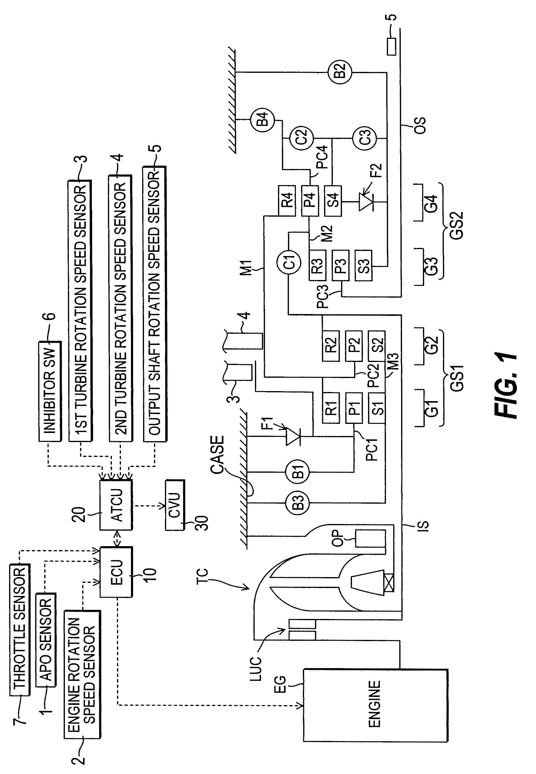
[0019]FIG. 1 is a skeleton diagram showing the constitution of an automatic transmission according to this embodiment. The automatic transmission of this embodiment is a stepped automatic transmission having seven forward speeds and one reverse speed, in which a drive force of an engine EG is input from an input shaft IS via a torque converter TC, varied in rotation speed by four planetary gears and seven friction elements, and output from an output shaft OS. An oil pump OP is provided coaxially with a pump impeller of the torque converter TC and driven to rotate by the drive force of the engine EG such that oil is pressurized.

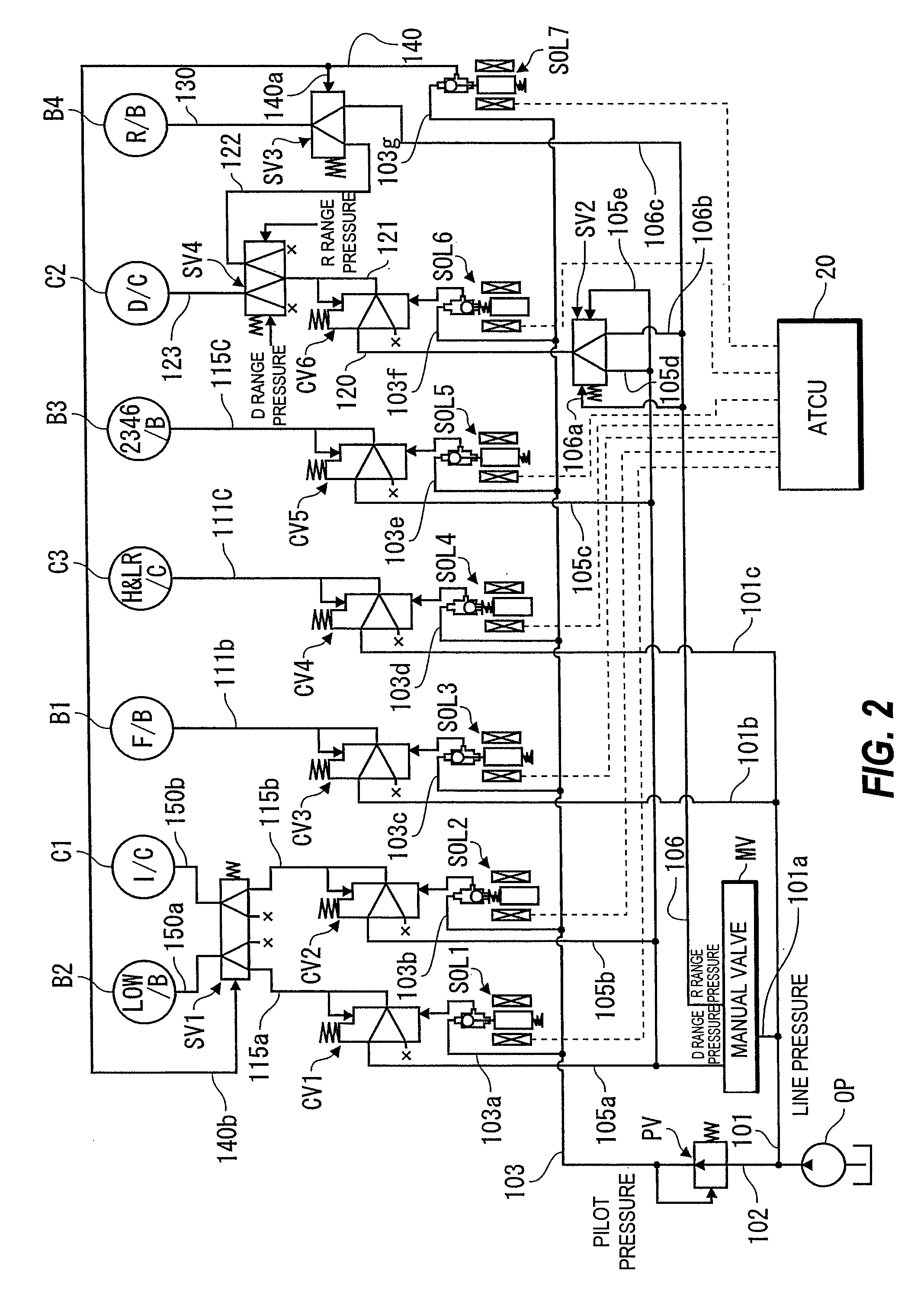
[0020]An engine controller (ECU) 10 that controls a driving state of the engine EG, an automatic transmission controller (ATCU) 20 that controls a gear position and so on of the automatic transmission and a control valve unit (CVU) 30 that controls an oil pre...


PUM


Abstract

In an automatic transmission of this invention, a determination as to whether or not a failure has occurred in a friction element is made repeatedly while a vehicle is traveling, and control to specify the failed friction element is begun when a vehicle speed falls to or below a predetermined value for the first time following detection of the failure in the friction element (S1, S3). When the failed friction element has been specified (S4, S13, S15, S24, S26, S35, S37), usable gear positions are determined on the basis of the specified friction element, whereupon shift control is performed using only the usable gear positions (S5, S14, S16, S25, S27, S36, S38, S39).

Description

TECHNICAL FIELD OF THE INVENTION[0001]This invention relates to failed element specification control employed when a failure occurs in a friction element of a stepped automatic transmission.BACKGROUND OF THE INVENTION[0002]A stepped automatic transmission comprises a planetary gear mechanism and a plurality of friction elements, and switches a gear position by switching an engagement state of each friction element such that a desired gear position is obtained.[0003]It is known that when a release failure or an engagement failure occurs in a friction element in this type of automatic transmission, control is performed to specify the failed friction element in order to secure drivability.[0004]For example, in a technique disclosed in JP11-280886A, characteristic data generated when a failure occurs in a friction element are stored in advance for each gear position, and on the basis of these stored data and an actual speed ratio, the failed friction element and the manner of the failur...

Claims


Application Information

Patent Timeline
Patent Type & Authority Patents(United States)
IPC IPC(8): F16H61/00F16H61/12
CPCF16H61/12Y10T477/675F16H2061/1224F16H61/686
Inventor NAGASHIMA, FUMITAKAKAWAGUCHI, TAKATERUMOCHIYAMA, SHINYASHINSO, YOSHIHIDE
Owner JATCO LTD
Learn More