
Radio apparatus and communication system

a technology of radio apparatus and communication system, applied in the field of radio apparatus, can solve the problems of increasing possibility and deteriorating reception characteristics, and achieve the effect of reducing the deterioration of receiving characteristics

Active Publication Date: 2012-07-17
HERA WIRELESS
View PDF11 Cites 2 Cited by
  • Summary
  • Abstract
  • Description
  • Claims
  • Application Information

AI Technical Summary

Benefits of technology

[0011]The present invention has been made in View of the foregoing circumstances and a general purpose thereof is to provide a radio apparatus and a communication system which reduce the deterioration in receiving characteristics of data placed in a posterior part of a packet signal even if the packet signal length becomes longer.
[0013]According to this embodiment, when a plurality of partial periods are assigned respectively to the terminal apparatuses, a terminal apparatus requiring a low data rate is assigned to a posterior partial period. Hence, the deterioration in the receiving characteristics can be prevented.
[0015]According to this embodiment, when a plurality of partial periods are assigned respectively to the terminal apparatuses, a terminal apparatus requiring a low data rate is assigned to a posterior partial period. Hence, the deterioration in the receiving characteristics can be prevented.
[0018]According to this embodiment, when a plurality of partial periods are assigned respectively to the terminal apparatuses, a terminal apparatus requiring a low data rate is assigned to a posterior partial period. As a result, the deterioration in the receiving characteristics can be prevented.

Problems solved by technology

In this case, when the length of packet signal becomes longer, the receiving characteristics deteriorate.
In particular, if the data for a plurality of terminal apparatuses are contained in a single packet signal, the possibility increases that a terminal apparatus which is to receive data placed in a posterior part of the packet signal cannot receive all of the data.

Method used


Image

  • Radio apparatus and communication system
  • Radio apparatus and communication system
  • Radio apparatus and communication system

Examples


Embodiment Construction

[0034]The invention will now be described based on the following embodiments which do not intend to limit the scope of the present invention but exemplify the invention. All of the features and the combinations thereof described in the embodiments are not necessarily essential to the invention.

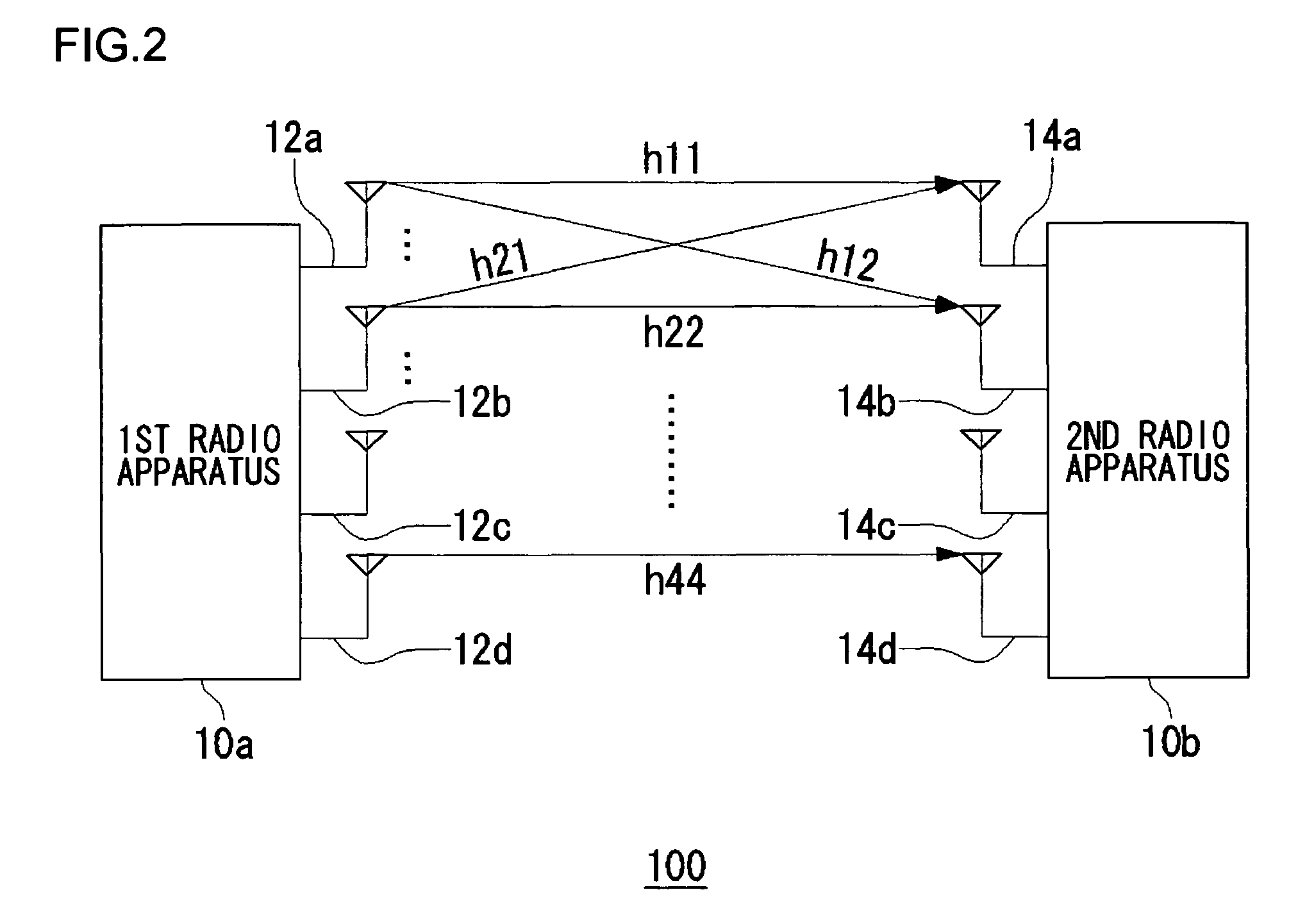
[0035]An outline of the present invention will be given before a detailed description thereof. The embodiments according to the present invention relate to a MIMO system comprised of a plurality of radio apparatuses. One of the radio apparatuses corresponds to a base station apparatus whereas the rest thereof correspond to a plurality of terminal apparatuses. The base station apparatus basically performs CSMA on a plurality of terminal apparatuses. In order to enhance the transmission efficiency, data for a plurality of terminal apparatuses are gathered up so as to generate one packet signal.

[0036]The present embodiment is based on the assumption that the speed of data for a terminal apparatus...


PUM


Abstract

A control unit generates packet signals while controlling an interface (IF) unit, a modulation unit and a baseband processing unit. While dividing each packet signal into a plurality of partial periods, the control unit assigns data to at least part of each of the plurality of partial periods and sets the rate of data, for a partial period placed anterior to each packet signal, higher than that for a partial period placed posterior to the each packet signal. The IF unit, the modulation unit and the baseband processing unit transmit the packet signals thus generated.

Description

RELATED APPLICATIONS[0001]This application claims the benefit of U.S. Provisional Patent Application No. 60 / 716,494, filed on Sep. 14, 2005 the disclosure of which application is incorporated by reference herein.BACKGROUND OF THE INVENTION[0002]1. Field of the Invention[0003]The present invention relates to radio apparatuses, and it particularly relates to a radio apparatus and a communication system using multiple subcarriers.[0004]2. Description of the Related Art[0005]An OFDM (Orthogonal Frequency Division Multiplexing) modulation scheme is one of multicarrier communication schemes that can realize the high-speed data transmission and are robust in the multipath environment. This OFDM modulation scheme has been applied to the wireless standards such as IEEE802.11a / g and HIPERLAN / 2. The packet signals in such a wireless LAN are generally transferred via a time-varying channel environment and are also subject to the effect of frequency selective fading. Hence, a receiving apparatus...

Claims


Application Information

Patent Timeline
Patent Type & Authority Patents(United States)
IPC IPC(8): H04J3/22H04J99/00H04W72/04
CPCH04B7/04H04L1/0003H04L1/0086H04L5/0064H04L25/0206H04L27/0008H04L27/2602H04L1/0009H04L5/0023H04L27/2613H04L5/0058H04L27/2603H04L25/0204
Inventor TANAKA, YASUHIRO
Owner HERA WIRELESS
Learn More