
Method and apparatus for measuring scattered light on an optical system

a technology of optical system and optical system, applied in the direction of optical radiation measurement, instruments, spectrometry/spectrophotometry/monochromators, etc., can solve the problem that the information regarding the scattered light portion of the optical system obtained with this method is often not sufficiently meaningful, and achieves meaningful scattered light measurement results.

Active Publication Date: 2012-07-10
CARL ZEISS SMT GMBH
View PDF12 Cites 2 Cited by
  • Summary
  • Abstract
  • Description
  • Claims
  • Application Information

AI Technical Summary

Benefits of technology

This approach provides more meaningful scattered light measurement results, enabling the characterization of anisotropic effects and preferred directions, allowing for improved optical system qualification, exposure correction, and identification of contamination sources.

Problems solved by technology

The information regarding the scattered light portion in the optical system obtained with this method is however often not sufficiently meaningful, in particular for microlithography.

Method used


Image

  • Method and apparatus for measuring scattered light on an optical system
  • Method and apparatus for measuring scattered light on an optical system
  • Method and apparatus for measuring scattered light on an optical system

Examples


Embodiment Construction

[0074]In the embodiments of the invention described below, components that are alike in function and structure are designated as far as possible by the same or like reference numerals. Therefore, to understand the features of the individual components of a specific embodiment, the descriptions of other embodiments or the summary of the invention should be referred to.

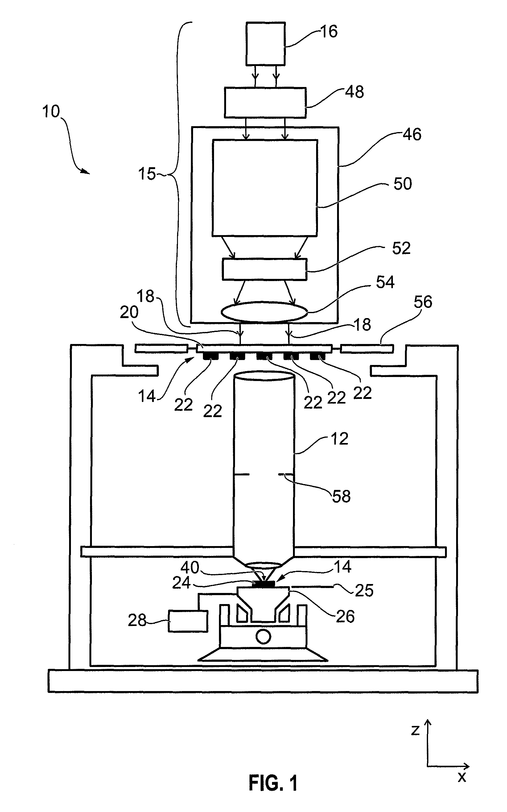
[0075]In FIGS. 1 and 8 different embodiments of exposure tools 10 for microlithography in the form of a projection exposure tool having an optical system 12 in the form of a projection objective are illustrated. In the following description reference is made to various elements of the exposure tool 10. Some of these elements may only be illustrated in one of FIGS. 1 and 8, however can be contained also in the embodiment of the other Figure. The projection exposure tool 10 shown in FIG. 1 is of a transmission type, i.e. it has a transmission mask 20, typically used with exposure light in the UV-wavelength region. A trans...


PUM

PropertyMeasurementUnit
wavelengthaaaaaaaaaa

Abstract

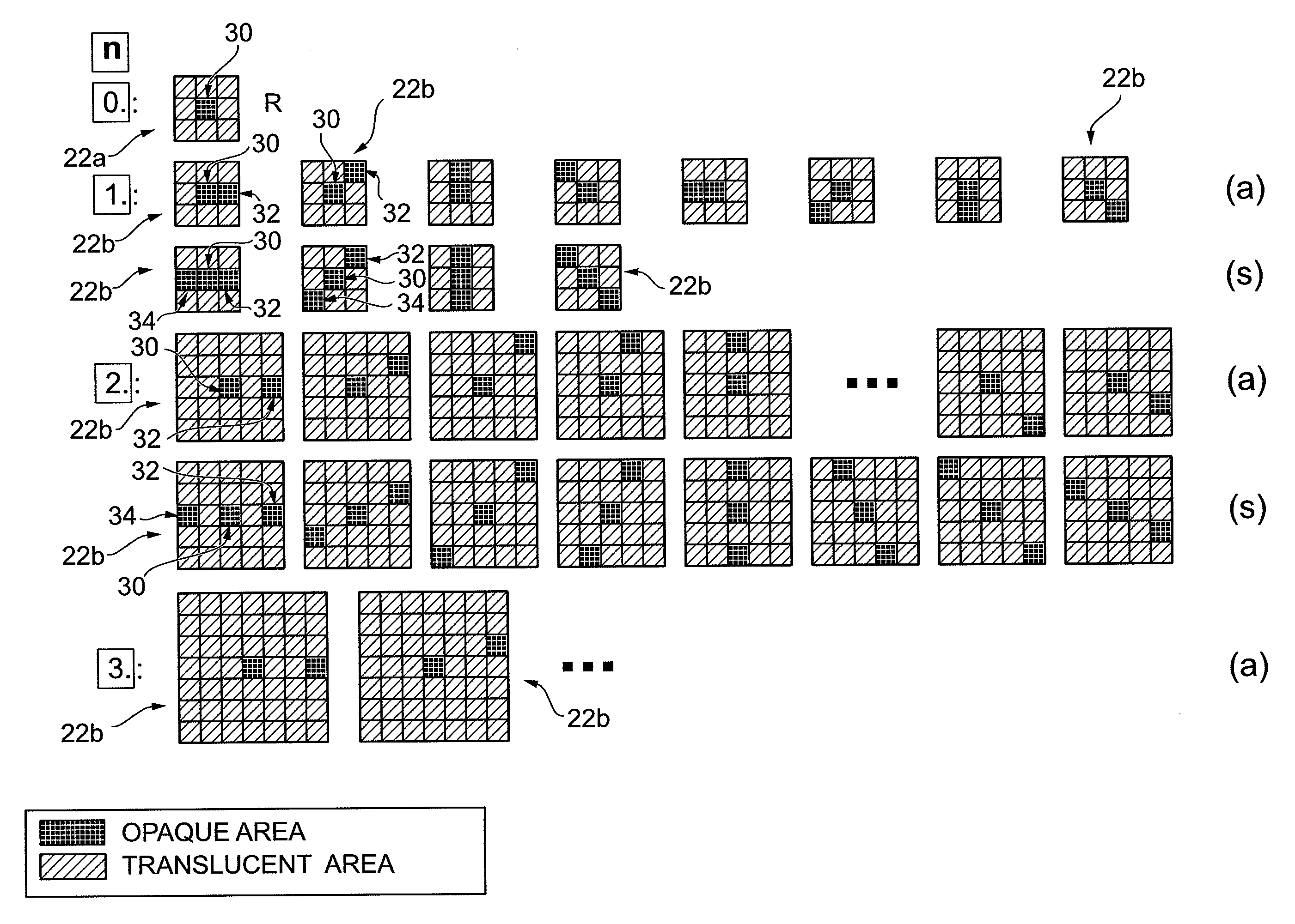
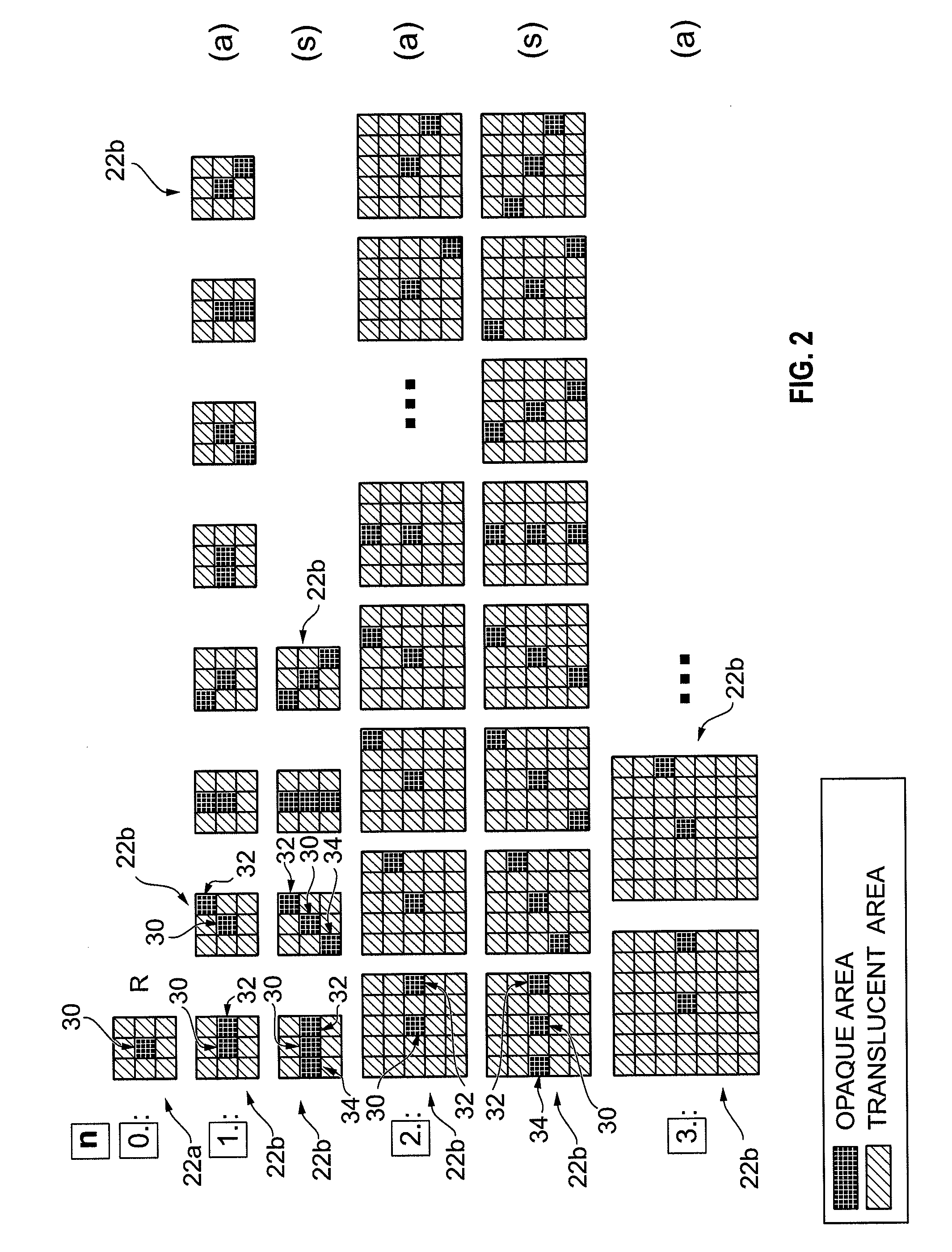
A method of measuring scattered light on an optical system includes: providing a first measuring field and a second measuring field, both measuring fields respectively being either of a first light manipulation type or a second light manipulation type, which first light manipulation type is configured to cause incoming light to enter the optical system and which second light manipulation type is configured to prevent incoming light from entering the optical system, and both measuring fields respectively having a second light manipulation type reference structure and a respective measuring structure, which measuring structures are of the second light manipulation type in the case where the measuring fields are of the first light manipulation type, and are first light manipulation type regions of the measuring fields in the case where the measuring fields are of the second light manipulation type, wherein the measuring structures of the respective measuring fields are offset in different directions in relation to the respective reference structure, imaging the first measuring field with the optical system into an image plane and measuring a first light intensity produced herewith at a location in the region of the image of the reference structure of the first measuring field, and imaging the second measuring field with the optical system into the image plane and measuring a second light intensity produced herewith at a location in the region of the image of the reference structure of the second measuring field.

Description

CROSS-REFERENCE TO RELATED APPLICATIONS[0001]This is a Continuation of International Application PCT / EP2008 / 006498, with an international filing date of Aug. 7, 2008, which was published under PCT Article 21(2) in English, and the complete disclosure of which is incorporated into this application by reference; this application also claims the benefit under 35 U.S.C. §119(e) of U.S. Provisional Application No. 60 / 955,065, filed Aug. 10, 2007, as well as the benefit of German Application No. 10 2007 038 057.9 filed Aug. 10, 2007, the entire disclosures of which are incorporated into this application by reference.FIELD OF AND BACKGROUND OF THE INVENTION[0002]The invention relates to a method and to an apparatus for measuring scattered light on an optical system. The invention further relates to a projection exposure tool for microlithography with this type of apparatus and to a mask for measuring scattered light on an optical system. Further the invention relates to a method of operati...

Claims


Application Information

Patent Timeline
Patent Type & Authority Patents(United States)
IPC IPC(8): G01N21/55
CPCG03F7/70941
Inventor ARNZ, MICHAEL
Owner CARL ZEISS SMT GMBH
Learn More