Device for performing analyses on biological fluids and related method

a technology for biological fluids and instruments, applied in biochemistry instruments and processes, biochemistry apparatus and processes, diagnostics, etc., can solve the problems of inability to perform biological fluid analysis in series, increase the complexity of the appliance and the corresponding cost of its management, and increase the risk of contamination between the samples analyzed in series

Active Publication Date: 2012-07-03
DIESSE DIAGNOSTICA SENESE
View PDF18 Cites 13 Cited by
  • Summary
  • Abstract
  • Description
  • Claims
  • Application Information

AI Technical Summary

Benefits of technology

[0005]An object of the invention is to realize a method for measuring erythrocyte sedimentation rate (ESR) that overcomes or reduces one or more of the drawbacks of the known methods.
[0012]Since the method according to the present invention involves measuring the erythrocyte sedimentation rate both in ESR-dedicated test tubes and in CBC-dedicated test tubes, without extracting the sample from the test tube, this can be done on a machine that processes both types of test tube and returns both types of result. Since the anticoagulant contained in the two test tubes is different, it must be possible to automatically or manually set up the procedure for processing the data obtained from the reading of the test tubes in order to take the type of anticoagulant contained in the samples into account. In the preferred embodiment of the method according to the invention, the type of test tube is detected automatically so that the entire measurement procedure can be automated without the operator needing to take action to specify the type of calculation to perform on the data obtained depending on the type of test tube used.
[0016]Alternatively, arrangements can be made to associate the test tubes with a transponder and to provide detection means, interfaced with the control unit of the analyzer, which interrogate the transponder. Data contained in the transponder enable the system to recognize the type of test tube loaded each time in the analyzer.
[0026]According to an advantageous embodiment, the second conveyor provided in the sedimentation area has a substantially horizontal stretch of straight path extending between the position where the racks are received from the magazine and a reading position. This stretch of straight path is situated substantially at the same height as a corresponding horizontal stretch of the conveyor forming the magazine. In this way, the racks containing the test tubes can be transferred from one conveyor to the other by a simple plunger.
[0040]Outside the agitating area, there may be fixed guides to avoid any vibration or accidental oscillation of the test tubes.
[0041]To achieve a reliable control of the device, according to an improved embodiment of the invention, the continuous flexible member includes a transponder associated with each test-tube holder. The transponder contains data that enable the recognition of each holder associated with a given test tube, which in turn is marked with information, attached by means of a label with a barcode, for instance, or other preferably machine-readable code, e.g. using an OCR reading system. A control unit associates the data in each transponder with the data on the test tube inserted in the respective holder. With a system for scanning the transponders in one or more suitable places along the path of the flexible member, it is consequently possible to identify the position of each test tube. The device thus becomes extremely reliable and error-free, even in the event of a temporary power failure, which might make the stepwise control system lose track of the position of the various test tubes along the path covered by the flexible member.

Problems solved by technology

They have considerable drawbacks, however, deriving from the fact that the blood sample must be drawn from the test tube by means of a pipette or capillary tube, which must subsequently be washed or replaced between one test and the next.
This involves the production of liquid or solid waste that has to be disposed of, consequently increasing the complexity of the appliance and the corresponding cost of its management, as well as the production costs.
Moreover, there is an inherent risk of contamination between the samples analyzed in series.

Method used


Image

  • Device for performing analyses on biological fluids and related method
  • Device for performing analyses on biological fluids and related method
  • Device for performing analyses on biological fluids and related method

Examples


Embodiment Construction

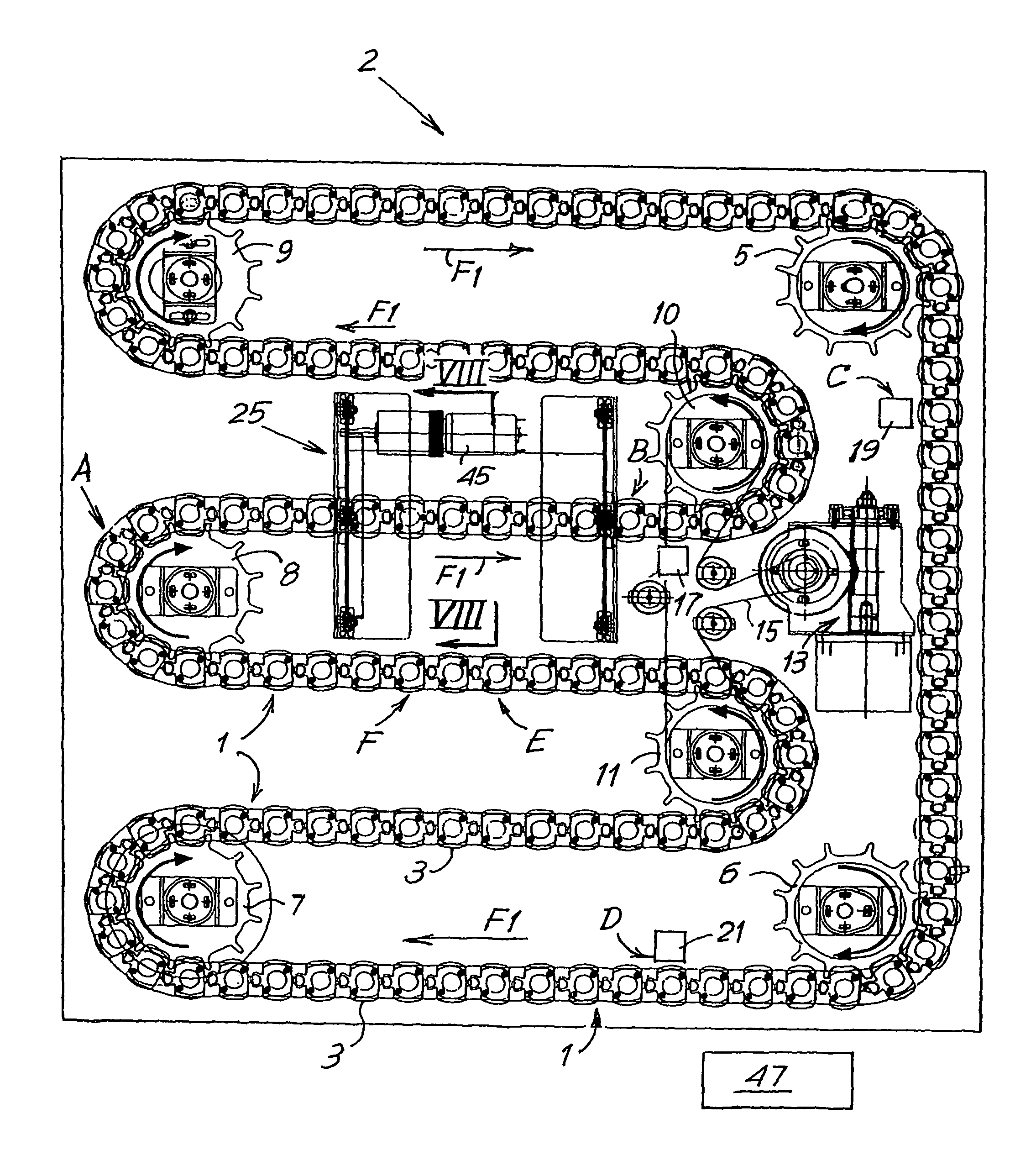
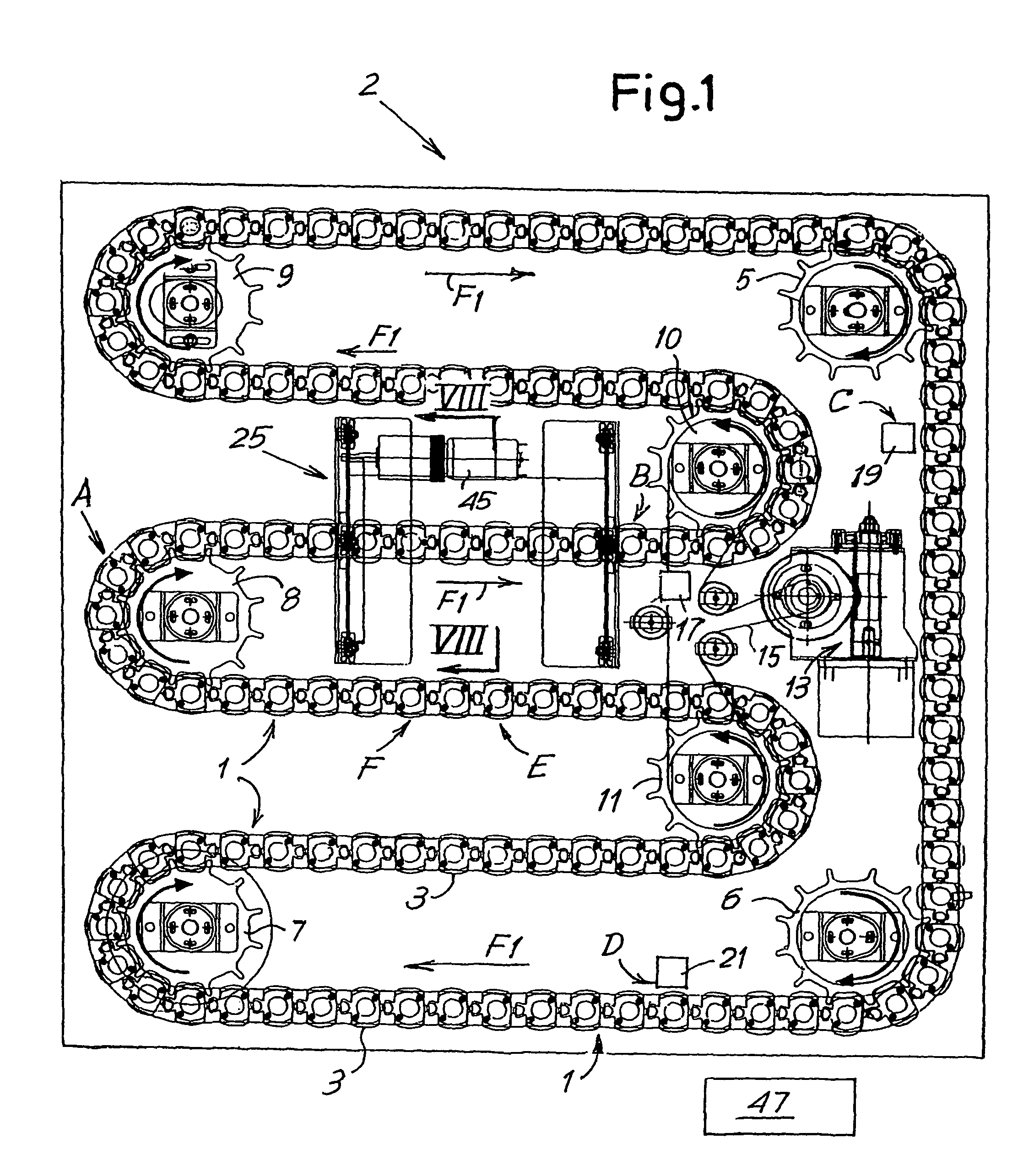
[0071]Referring to the drawings in particular, FIGS. 1 through 18 the first embodiment, the device comprises two sections or units: the agitation, sedimentation and reading section or unit, comprising the flexible member with the holders for the test tubes, and a section or unit installed over it hereinafter called the setup unit. The latter could be omitted in the case of a more economical, less automated device. In the following paragraphs, the unit underneath, with the agitation, sedimentation and reading elements, is described first, followed by the optional setup unit with the respective means for transferring the test tubes.

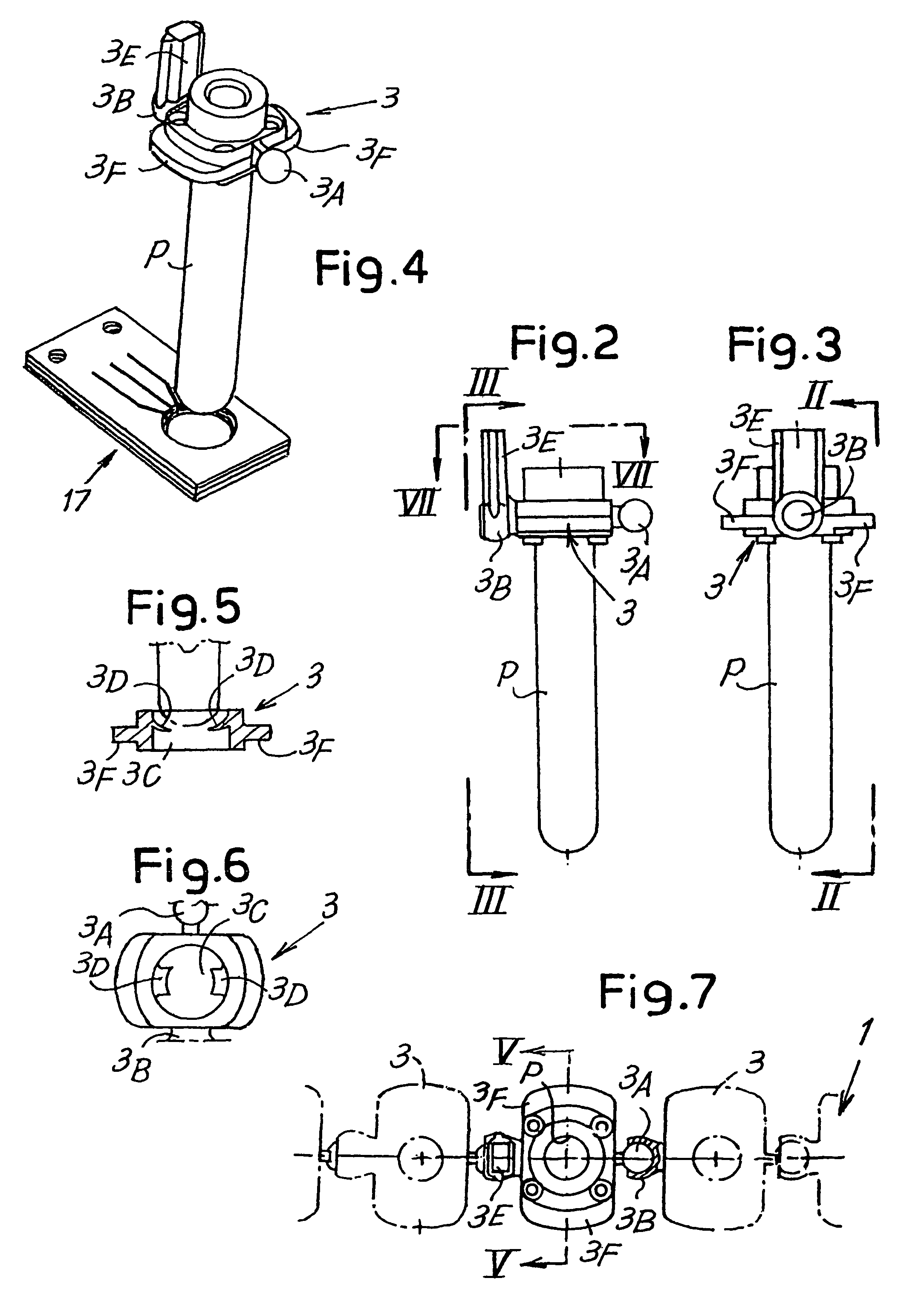
[0072]Referring initially to FIGS. 1 to 11, the lower unit in the device, globally indicated by the numeral 2, comprises a flexible member composed of a chain formed by a series of single elements 3 that will be described in detail with reference to FIGS. 2 to 7. Each element 3 has a seat or holder for a respective test tube P, such that a plurality of test...


PUM

PropertyMeasurementUnit
flexibleaaaaaaaaaa
sedimentation areaaaaaaaaaaa
areaaaaaaaaaaa

Abstract

A device for measuring the sedimentation rate in biological fluids, and particularly the erythrocyte sedimentation rate in blood samples. The device comprises: holders (3) for test tubes (P) containing samples of biological fluid; agitator devices (25) for agitating the test tubes; at least one detector (17, 19) for reading the levels inside the test tubes. The holders together form a continuous flexible member (1) defining a closed path along which the agitator devices and the detector are arranged.

Description

CROSS REFERENCE TO RELATED APPLICATIONS[0001]This application claims the benefit of priority under 35 U.S.C. §119 of FI2003A000273 filed Oct. 28, 2003, the entire contents of which are incorporated herein by reference.FIELD OF THE INVENTION[0002]The present invention relates to a device or appliance for measuring biological fluids, and particularly for measuring the sedimentation of particles in biological fluids, especially for measuring the erythrocyte sedimentation rate. The invention also relates to a method for taking said measurements.BACKGROUND OF THE INVENTION[0003]The erythrocyte sedimentation rate is measured as part of the routine analyses performed on blood samples. This analysis can normally be performed using test tubes or cuvettes with a particular shape, suitable for optical reading by means of a transmitter-receiver that slides axially along the test tube. An example of a test tube suitable for this application is described in EP-B-898700. Appliances that use dedica...

Claims


Application Information

Patent Timeline
Patent Type & Authority Patents(United States)
IPC IPC(8): G01N31/22B01L9/06B01L99/00G01N15/00G01N15/05G01N35/00G01N35/02G01N35/04
CPCB01L9/06G01N15/05G01N35/021B01L2200/028B01L2300/123Y10T436/113332G01N2015/0073G01N2035/00524G01N2035/0408G01N35/00732G01N33/49G01N33/00G01N35/00G01N35/02
Inventor RICCI, ANTONIOMELONI, MICHELECOCOLA, FRANCESCO
Owner DIESSE DIAGNOSTICA SENESE
Why Eureka
Try Eureka