
Pneumatic adjustable-height table

a technology of pneumatic adjustment and height table, which is applied in the direction of adjustable height table, stand/trestle, kitchen equipment, etc., can solve the problems of universally difficult to change from one height to another, and continue to generate dissatisfaction among users

Inactive Publication Date: 2012-07-03
DEWEES THOMAS GERRET
View PDF47 Cites 28 Cited by
  • Summary
  • Abstract
  • Description
  • Claims
  • Application Information

AI Technical Summary

Benefits of technology

[0008]In its several embodiments this invention is a system which includes a base designed to rest on the floor or other supporting surface, a table top and a relatively frictionless means to raise and guide the table top from a coffee table height, such as 18 inches, to a dining table height, such as 29 inches. Other possible height ranges include table height to a height appropriate for standing. A means is also included to provide a lifting force sufficient to support slightly more than the weight of the table top assembly, preferably with a net light lifting force. This lifting force is such that little or no effort is required from the user to raise the table and only light downward pressure is required to return the table to a lower position. A means of locking and unlocking the vertical movement of the table in an infinite plurality of vertical positions is also included. A relatively frictionless guiding mechanism maintains vertical alignment and a stable relationship between the table top and the base.
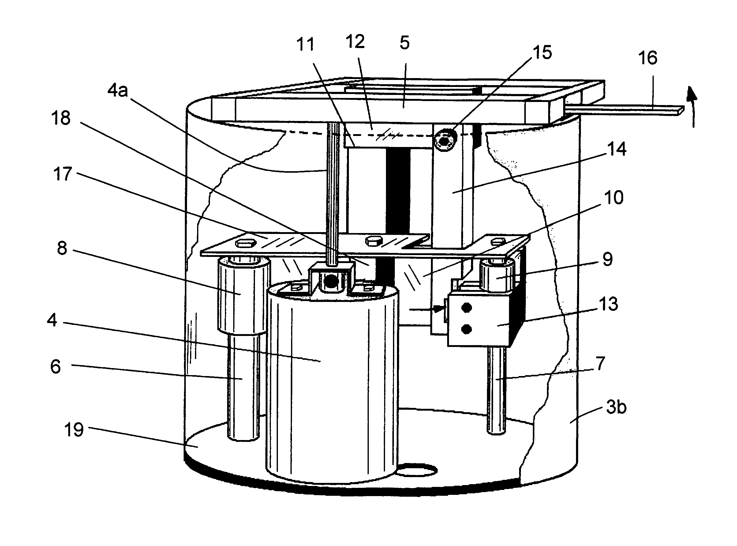
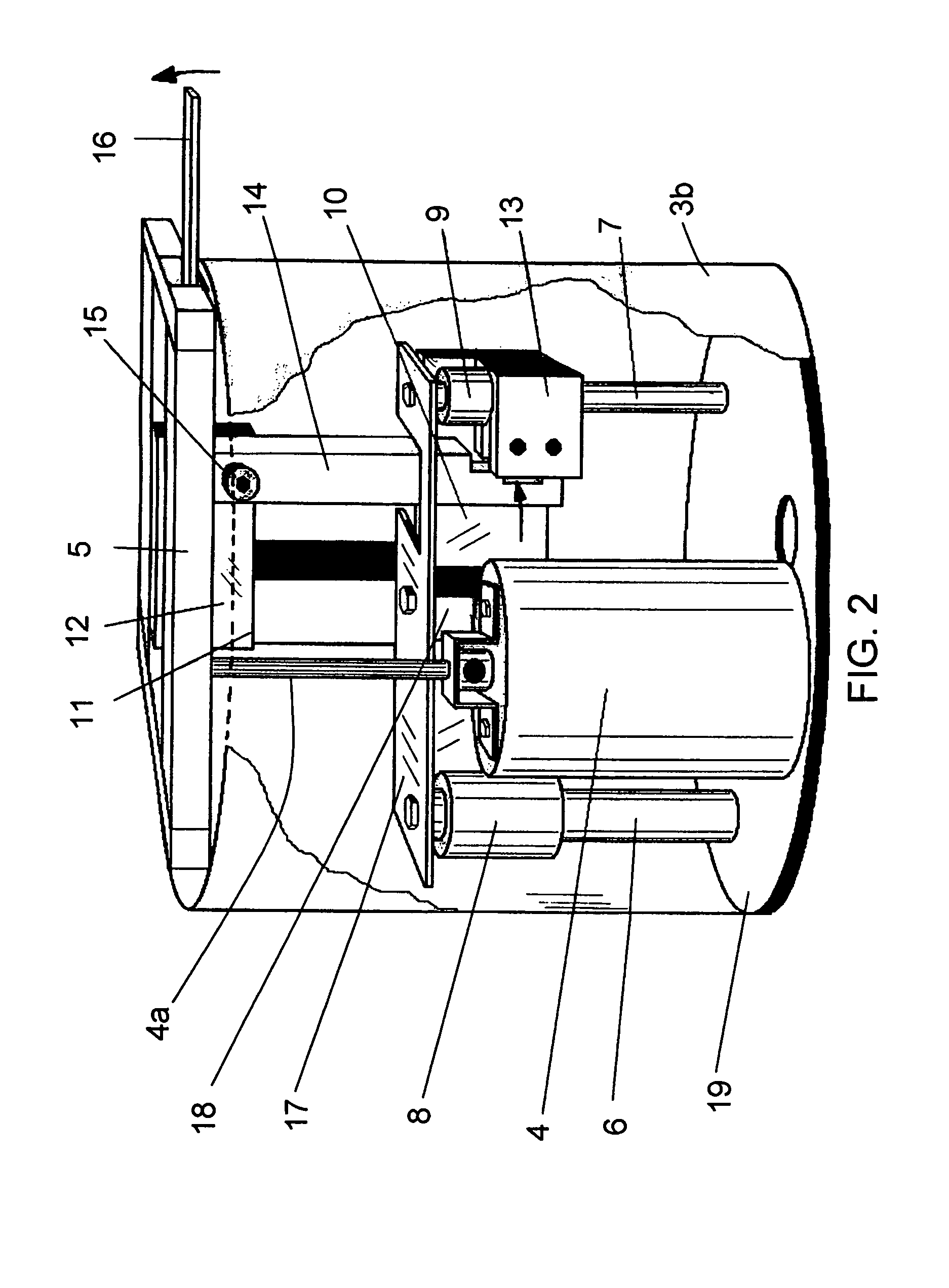
[0009]In the preferred embodiment frictionless linear bearings sliding vertically on one or more suitable shafts provide the required guidance and stabilization and one or more air cylinders connected to one or more pressurized air reservoirs provide a lifting force. A further aspect of the preferred embodiment uses a large sealed tubular tank member into which an air cylinder is directly mounted with the rod end of the cylinder projecting out of the tank. The tank end is sealed around the body of the air cylinder by means such as multiple o-rings and the air cylinder is held in place, preferably down in the tank so as to be integral with the tank, by means of a suitable bracket fastened securely to the tank. The rod end of the air cylinder is open to the atmosphere and the other end is in and open to the interior of the tank. This end of the air cylinder is therefore pressurized to the amount of pressure established in the tank. A suitable means, such as an automotive type air valve assembly, is provided for introducing air into the tank to bring the pressure to the desired amount. The integral mounting of the air cylinder into the tank eliminates numerous pipe fittings and pipes and / or hoses which would otherwise be required to connect the cylinder to the tank to form a closed system as taught by Haller in U.S. Pat. No. 6,283,047. The benefits include reduced chances of air leakage and reduced manufacturing costs.
[0013]Also in the preferred embodiment of the invention the air cylinder or cylinders are oriented to provide the lifting force by upward cylinder rod extension. By this orientation cylinder rod seals are eliminated from the sealed pressurized system and rod seal leakage cannot affect the pressurization of the system. Since in this orientation the rod end of the cylinder or cylinders face upward and the upper end of the cylinder or cylinders are left open to the atmosphere, appropriate lubrication can be introduced into the open port on the rod end. Also in this embodiment of the invention a plug having a hole of appropriate size drilled through it is inserted into the open port on the rod end to control the rate of air flow in and out of the atmospheric end of the air cylinder or cylinders and thus to control the rate of vertical movement of the table top assembly.

Problems solved by technology

Although these designs currently on the market can fill the basic requirement of coffee table height and dining table height, they are universally difficult to change from one height to another and are generally limited to two specific predetermined heights.
They continue to generate dissatisfaction among those who use them.

Method used


Image

  • Pneumatic adjustable-height table
  • Pneumatic adjustable-height table
  • Pneumatic adjustable-height table

Examples


Embodiment Construction

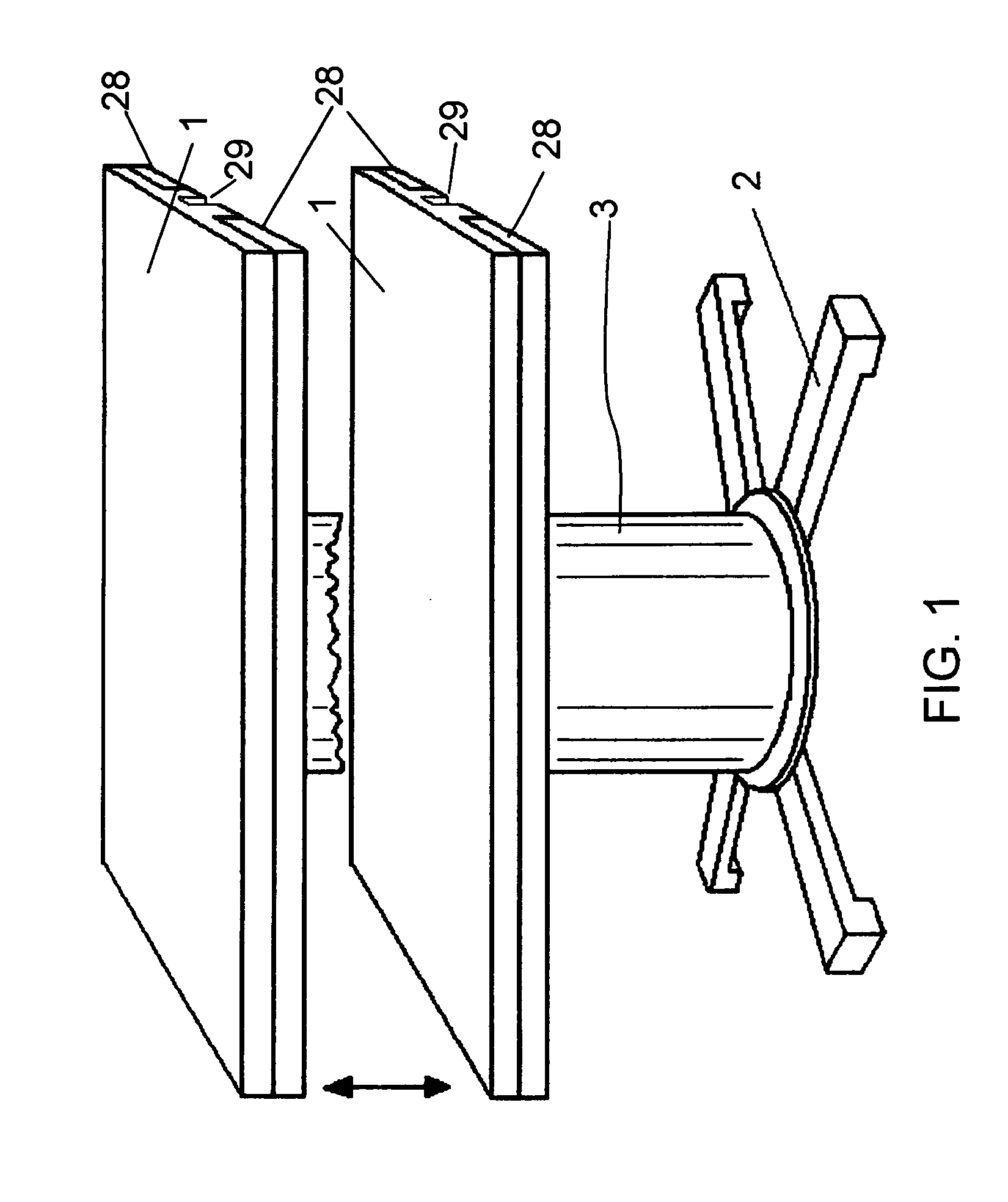
[0022]The present invention provides a convenient system for raising a table top 1 as shown in FIG. 1 from a low position such as an 18 inch coffee table height to a higher position such as a 29 inch dining table height (or with other height limits), relative to a mounting base 2, by means of a pneumatic system enclosed for cosmetic purposes in a shroud assembly consisting of two telescoping parts 3. Only the outer shroud component 3 is seen in FIG. 1; an inner component can extend upward from the base 2, just inside the illustrated component 3, which is secured to and moves with the table. FIG. 1 also shows that the base 2 includes a floor-engaging pedestal. The base 2 is removable from the base plate 19 seen in FIG. 2 and interchangeable via several bolts (not shown) to a different style or configuration or material of floor-engaging element.

[0023]As shown in FIG. 2 and in exploded view FIG. 2A, the invention embodies a system in which an integrated air cylinder and tank assembly ...


PUM


Abstract

An adjustable table is easily moved from coffee table height to dining table. The weight of the table top is supported by a pneumatic cylinder, preferably exerting a force slightly greater than the weight of the table top. The cylinder connects to a much larger air tank, so that essentially constant lifting force is exerted. For stability of the table top a guide mechanism firmly retains the table against rotation, side movement or tilting. A unique locking mechanism retains the table at a selected height and is easily released with a finger lever.

Description

[0001]This application claims benefit from provisional application Ser. No. 60 / 984,668, filed Nov. 1, 2007.BACKGROUND OF THE INVENTION[0002]The present invention relates to a design of a table which serves multiple purposes as a coffee table and / or dinner table. For this purpose the table is vertically adjustable from a low coffee table height, such as 18 inches, continuously up to a dining table height, such as 29 inches. Other height ranges can also be encompassed, such as a table height for standing use.[0003]In the majority of motor homes and other recreational vehicles currently produced the design focus is on providing a social gathering area which must double as a dining area because of limited space. This gives rise to the need for a table which can serve the dual purpose of a coffee table and a dining table. The present invention addresses this need by providing a table that can be easily raised from coffee table height to dining table height.[0004]Other areas where this pr...

Claims


Application Information

Patent Timeline
IPC IPC(8): A47B9/00F16M11/24
CPCA47B9/10A47B2009/006
Inventor DEWEES, THOMAS GERRET
Owner DEWEES THOMAS GERRET
Learn More