Ferrite filter comprising aperture-coupled fin lines

a technology of aperture-coupled fins and filters, which is applied in the direction of resonators, basic electric elements, electric devices, etc., can solve the problems of unfavorable field distribution of wave to be decoupled, unfavorable energy transport by the incoming wave, and disturbance of auxiliary modes by coupling, so as to reduce the cost of adjustment, facilitate the assembly of filters, and avoid the cost of attaching an appropriate mounting.

Active Publication Date: 2012-06-26
ROHDE & SCHWARZ GMBH & CO KG
View PDF6 Cites 1 Cited by
  • Summary
  • Abstract
  • Description
  • Claims
  • Application Information

AI Technical Summary

Benefits of technology

[0024]A mirror-image arrangement of the resonator spheres on both sides of the coupling aperture is also preferred, because this contributes to reducing the cost of adjustment. In particular, it is preferred if the resonator spheres are each glued directly onto the substrate layer, thereby avoiding the cost of attaching an appropriate mounting, which, once again, preferably facilitates the assembly of the filter according to the invention.
[0025]One further advantage of the filter according to the invention is that the resonator spheres in the filter arms are arranged with different internal structures. Accordingly, a magnetically-tunable filter according to the invention, which consists of an aperture-coupled microstripline and a unilateral fin line, achieves a stretched geometry with a reduced overall height. The filter according to the invention is therefore easier to install as a whole in a narrow slit between the pole shoes of an electromagnet. With a small distance between the pole shoes, high magnetic-field strengths can be generated at a reduced cost and therefore more readily. A small spacing distance preferably has a positive effect on the homogeneity of the DC magnetic field.

Problems solved by technology

As a result, disturbing auxiliary modes can be excited by the coupling.
One disadvantage of the variable band-pass filter described in U.S. Pat. No. 4,888,569 B1 is that in resonant conditions, the field distribution of the wave to be decoupled is unfavorable in the coupling region, because the wave is conducted in a waveguide, of which the profile tapers towards the coupling region in a direction perpendicular to the direction of propagation of the wave to be decoupled.
As a result, undesirable reflections occur, which overlap in a destructive manner and therefore reduce the amount of energy transported by the incoming wave.
One further disadvantage is the limited bandwidth of the waveguide concept.

Method used


Image

  • Ferrite filter comprising aperture-coupled fin lines
  • Ferrite filter comprising aperture-coupled fin lines
  • Ferrite filter comprising aperture-coupled fin lines

Examples


Embodiment Construction

[0056]By way of explanation of the magnetically-tunable filter according to the invention, the following section initially describes the structures conventional at the time of the invention and their disadvantages with reference to FIGS. 1 to 8. With reference to FIG. 9, a first exemplary embodiment of the magnetically-tunable filter 1 according to the invention will then be described in greater detail. In the description of the formerly-conventional structures and of the exemplary embodiments of the present invention, identical reference numbers will be used for functionally-identical elements.

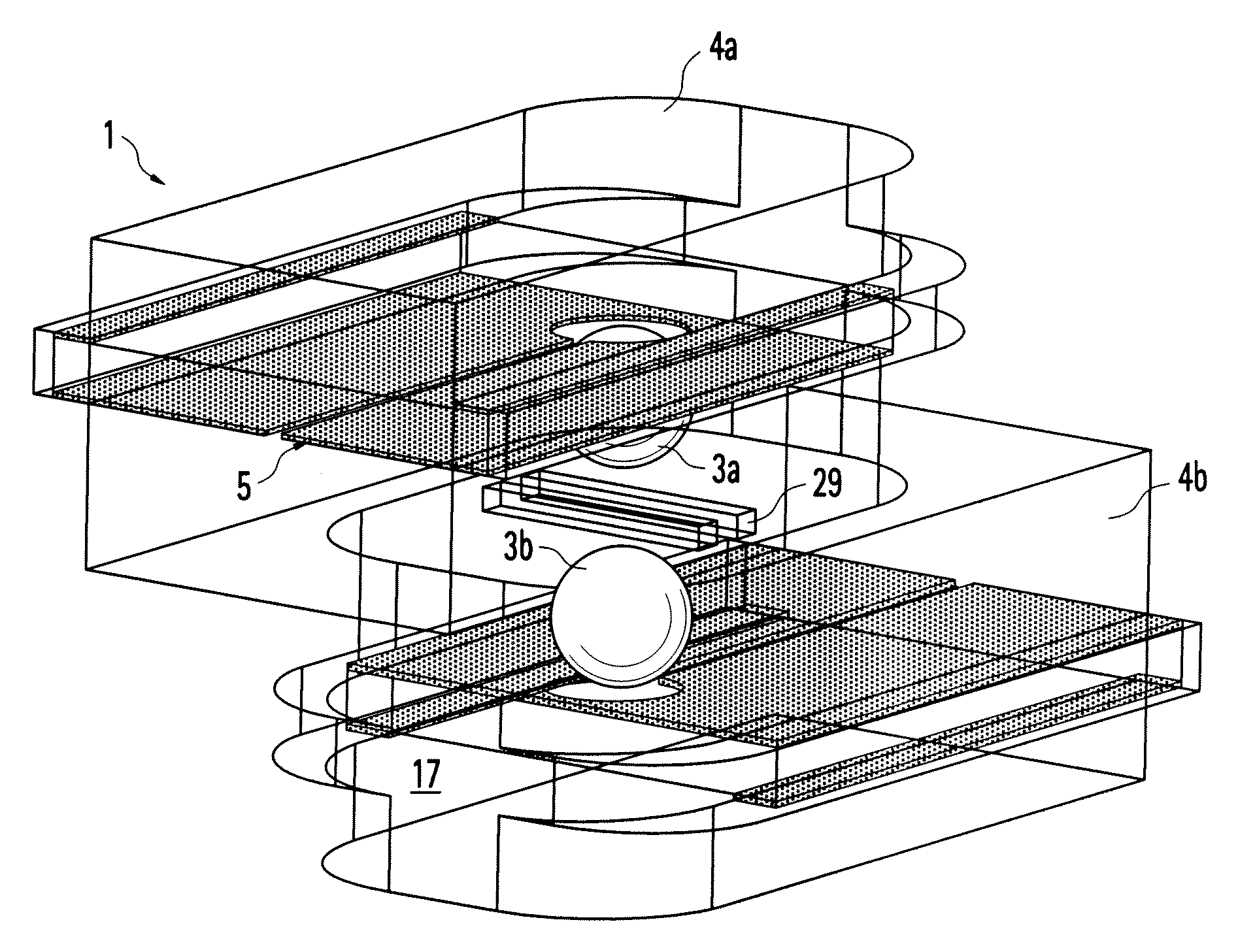
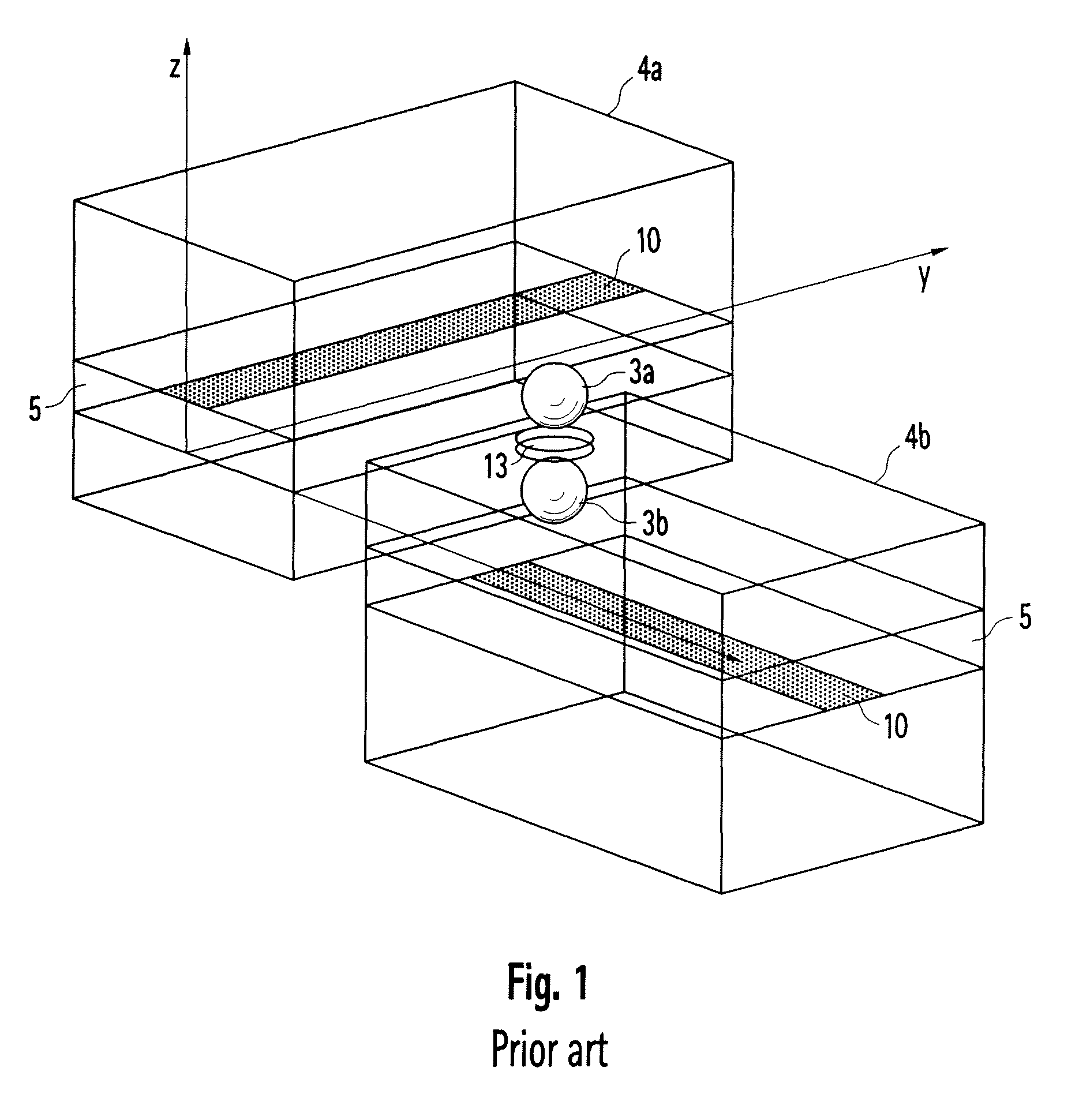
[0057]FIG. 1 shows a formerly-conventional structure of aperture-coupled, shielded (suspended) striplines, wherein a coupling structure consisting of two resonator spheres 3a, 3b disposed one above the other and separated by an apertured diaphragm 13 is used for coupling connecting resonators.

[0058]The external DC magnetic field H0 for tuning the resonance frequency is aligned parallel to the...


PUM


Abstract

A magnetically-tunable filter comprising a filter housing with two tunable resonator spheres made of magnetizable material, which are disposed one above the other in two filter arms. At least one filter arm provides a fin line or slot line disposed on a substrate layer and extending in the direction towards an electrical contact, and a common coupling aperture, thereby connecting the two filter arms to one another. In this context, one resonator sphere is positioned within each filter arm on each of the two sides of the coupling aperture.

Description

BACKGROUND OF THE INVENTION[0001]According to the prior art, tunable band-pass filters comprise resonator elements made of ferrites, in which the resonance frequency is adjusted via an external DC magnetic field. The resonators are generally spherical, because this shape can be manufactured using relatively-simple techniques with the dimensions required for use at high frequencies (diameter of sphere ≦0.3 mm). One reason for using spherical resonators is the linear relationship between the resonance frequency and the modulus of the external DC magnetic field.[0002]Yttrium iron garnet (YIG) is used as the material for the resonators at frequencies up to approximately 50 GHz. For frequencies above 50 GHz, the use of hexaferrites has proved preferred. Because of their crystalline structure, hexaferrites provide an anisotropic field, which, with a corresponding orientation relative to the external DC magnetic field, allows the adjustment of high resonance frequencies with significantly-...

Claims


Application Information

Patent Timeline
Patent Type & Authority Patents(United States)
IPC IPC(8): H01P1/218H01P7/00
CPCH01P1/218
Inventor STERNS, MICHAELSCHNEIDERBANGER, DIRKREHNER, ROBERTSCHMIDT, LORENZ-PETER
Owner ROHDE & SCHWARZ GMBH & CO KG
Why Eureka
Try Eureka