
Camera module and method of manufacturing camera module

a technology of camera module and manufacturing method, which is applied in the field of camera module, can solve the problems of hardly using photo-curing resin and variable relative position, and achieve the effects of ensuring the strength of joining, improving the alignment accuracy of the relative position of the sensor package to the lens structure, and short curing tim

Active Publication Date: 2012-06-19
LAPIS SEMICON CO LTD
View PDF5 Cites 1 Cited by
  • Summary
  • Abstract
  • Description
  • Claims
  • Application Information

AI Technical Summary

Benefits of technology

The present invention provides a camera module with a sensor package and a lens structure, and a method of manufacturing the camera module. The method includes applying a photo-curing resin to the receptacle, aligning the sensor package with the lens structure, and curing the resin to fix the sensor package in place. This ensures accurate alignment between the sensor package and the lens structure. The camera module includes a first joint and a second joint, and the sensor package is fixed within the receptacle using both resins. This method improves the accuracy of the relative position between the sensor package and the lens structure, and ensures strong joining strength.

Problems solved by technology

In the case that thermosetting resin is used for joining the lens structure to the sensor package, the following problem has occurred: since relatively long time is taken for heat curing, a relative position of the lens structure to the sensor package is hard to be held during heat curing, leading to variation in the relative position.
Therefore, the joint is hardly irradiated with light for curing resin, leading to a problem that the photo-curing resin has been hardly used.

Method used


Image

  • Camera module and method of manufacturing camera module
  • Camera module and method of manufacturing camera module
  • Camera module and method of manufacturing camera module

Examples


Embodiment Construction

[0038]Hereinafter, an example of the present invention will be described with reference to drawings. In the following figures, substantially equal or equivalent components or portions are indicated with the same references.

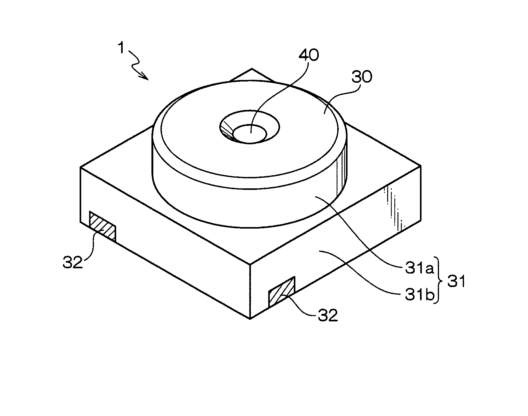
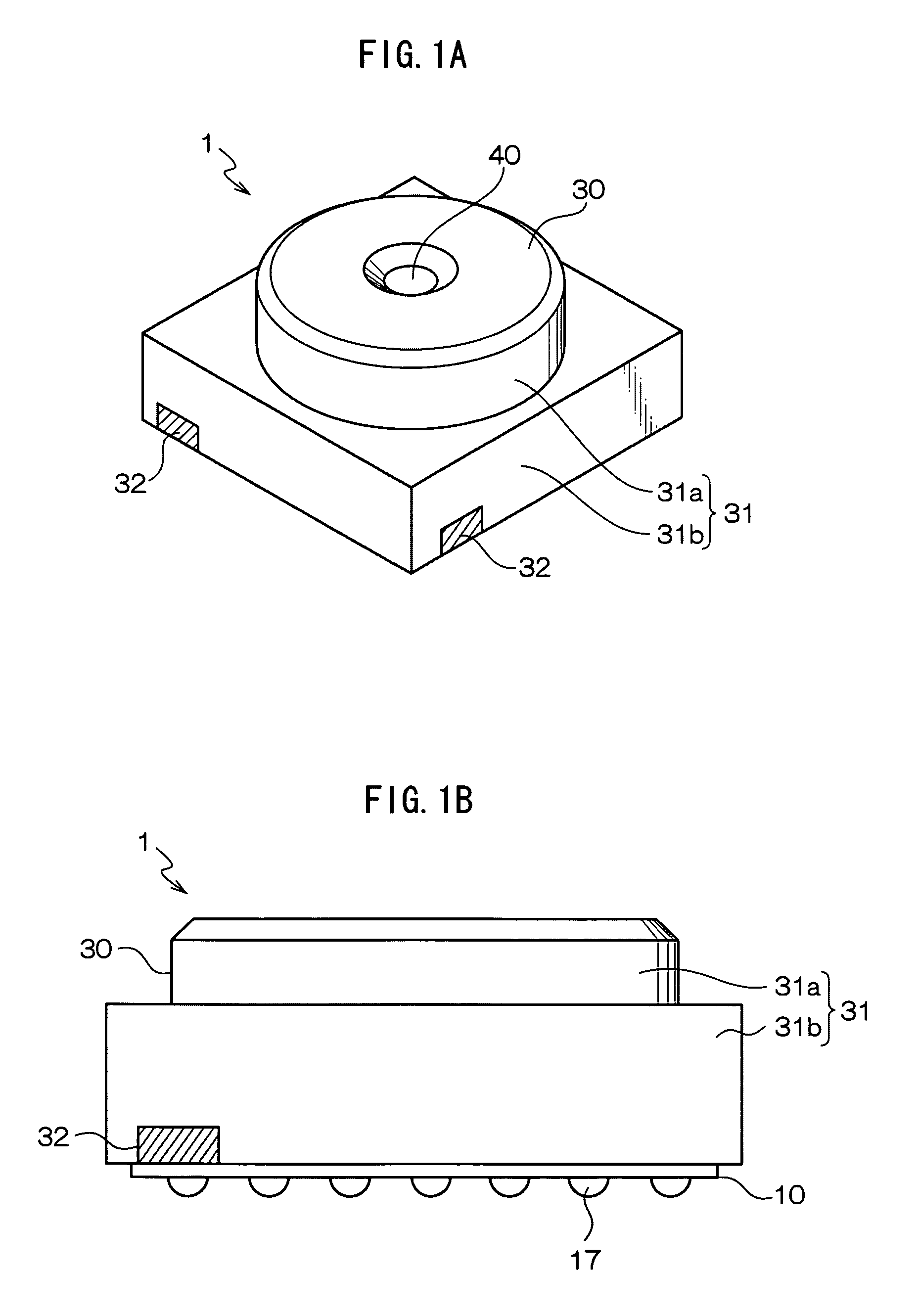
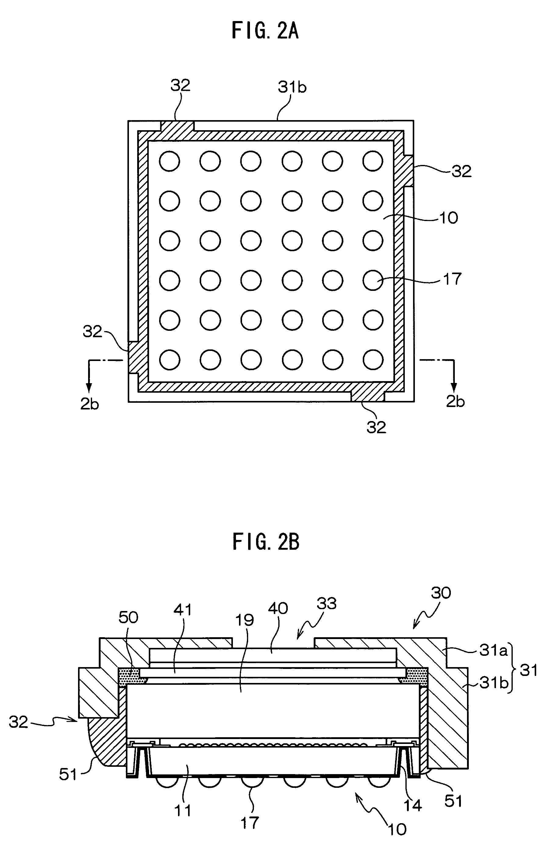
[0039]FIG. 1A is a perspective view of a camera module 1 as an example of the invention. FIG. 1B is a side view of the camera module. FIG. 2A is a plan view of the camera module as viewed from a back side thereof. FIG. 2B is a section view along a line 2b-2b in FIG. 2A. FIG. 3A is a section view of a sensor package 10 configuring the camera module 1. FIG. 3B is a section view of a lens structure 30 configuring the camera module 1.

[0040]First, a configuration of the sensor package 10 used for the camera module 1 as the example of the invention will be described with reference to FIG. 3A.

[0041]The sensor package 10 includes a semiconductor substrate 11 on which many image pickup elements such as CMOS sensors or CCD sensors are formed only at the number of pixels. Ea...


PUM

PropertyMeasurementUnit
distanceaaaaaaaaaa
timeaaaaaaaaaa
sizeaaaaaaaaaa

Abstract

There is provided a method of manufacturing a camera module including a sensor package having an image pickup element, and a lens configuration in which a lens holder, and a receptacle accommodating the sensor package are integrally formed, the sensor package being fixed within the receptacle, the method including: applying a photo-curing resin to predetermined portions of the receptacle; performing alignment of a relative position of the sensor package to the lens configuration; a first joining whereby the photo-curing resin is cured so that the sensor package is fixed within the receptacle while maintaining the relative position of the sensor package to the lens configuration; and a second joining whereby a thermosetting resin is applied so as to fill a space formed between the sensor package and the lens configuration, and then curing the thermosetting resin.

Description

CROSS-REFERENCE TO RELATED APPLICATION[0001]This application is based on and claims priority under 35 USC 119 from Japanese Patent Application No. 2008-208887 filed on Aug. 14, 2008, the disclosure of which is incorporated by reference herein.BACKGROUND[0002]1. Technical Field[0003]The present invention relates to a camera module in which image pickup elements and an optical component such as a lens are integrally formed.[0004]2. Related Art[0005]In a mobile device such as mobile phone, a model having a built-in camera is now mainstream. A camera mounted in such a mobile device is required to have small size and small thickness. To achieve this, a camera module is being developed, in which an optical component such as a lens and solid image pickup elements such as CMOS sensors are integrally formed.[0006]Recently, the mobile device tends to be reduced in size more and more, and accordingly further size reduction is required for a camera module. To achieve this, each image pickup ele...

Claims


Application Information

Patent Timeline
Patent Type & Authority Patents(United States)
IPC IPC(8): B32B37/00G02B7/02H01L27/14H04N25/00
CPCG02B7/025H01L27/14618H01L27/14625H01L31/0232H04N5/2253H04N5/2254H04N5/2257H01L2224/13H01L2224/05548H01L2224/05573H01L2224/05647H01L31/02325H01L2924/00014H01L2224/0554H01L2224/06131H04N23/54H04N23/57H04N23/55H01L2224/05599H01L2224/0555H01L2224/0556
Inventor EGAWA, YOSHIMI
Owner LAPIS SEMICON CO LTD
Learn More