
Amplitude sensitive damper apparatus

a damper and amplitude technology, applied in the direction of shock absorbers, vibration dampers, springs/dampers, etc., can solve the problems of increased production cost, impact noise generation, and springs that do not normally operate, and achieve the effect of reducing the impact noise generated between the spool member and the piston rod

Inactive Publication Date: 2012-06-19
HYUNDAI MOTOR CO LTD
View PDF14 Cites 14 Cited by
  • Summary
  • Abstract
  • Description
  • Claims
  • Application Information

AI Technical Summary

Benefits of technology

[0016]Various aspects of the present invention are directed to provide an amplitude sensitive damper apparatus that reduces impact noise that is generated at an amplitude sensitive valve and that has an improved structure to be light and compact.
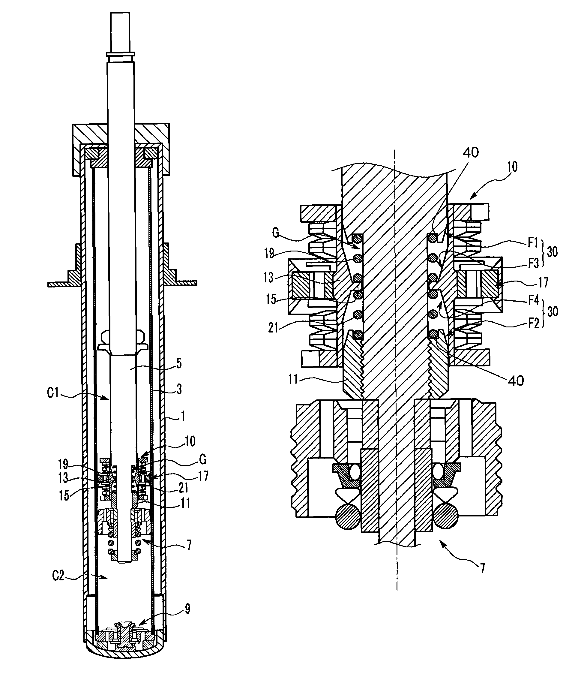
[0024]Further, since the corresponding slanted surfaces are formed respectively on the spool member and the piston rod, the impact noise that is generated between the spool member and the piston rod can be reduced when the stroke size (swing amplitude) of the piston is large (high).

Problems solved by technology

Then, if the damping force is much higher than the repellent force of the spring, there is a problem in which the damper restricts the elastic deformation of the spring such that the spring does not normally operate.
However, when the piston rod swings with the high amplitude, there is a drawback in that impact noise is generated between the retainer 113 and the amplitude sensitive valve 117, and the inner and outer springs S1 and S2 are applied in the upper and lower portions of the amplitude sensitive valve 117 such that the overall weight and the production cost are increased.

Method used


Image

  • Amplitude sensitive damper apparatus
  • Amplitude sensitive damper apparatus
  • Amplitude sensitive damper apparatus

Examples


Embodiment Construction

[0031]Reference will now be made in detail to various embodiments of the present invention(s), examples of which are illustrated in the accompanying drawings and described below. While the invention(s) will be described in conjunction with exemplary embodiments, it will be understood that present description is not intended to limit the invention(s) to those exemplary embodiments. On the contrary, the invention(s) is / are intended to cover not only the exemplary embodiments, but also various alternatives, modifications, equivalents and other embodiments, which may be included within the spirit and scope of the invention as defined by the appended claims.

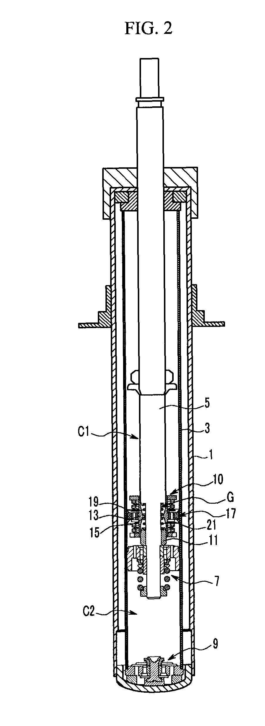
[0032]FIG. 2 is a cross-sectional view of an amplitude sensitive damper apparatus according various embodiments of the present invention, and FIG. 3 is an expanded cross-sectional view of an amplitude sensitive valve unit that is applied in an amplitude sensitive damper apparatus according to various embodiments of the present inventi...


PUM


Abstract

An amplitude sensitive damper apparatus that is provided with an amplitude sensitive valve unit may include a plug coupled to a piston rod to form a spring groove with the piston rod in a predetermined section, a spool member configured and dimensioned to cover the spring groove and slidably coupled to the piston rod to move up and down along the piston rod, wherein the spool member includes a supporting portion that protrudes toward the piston rod from a middle portion of an inner surface of the spool member, upper and lower elastic members that are mounted inside the spring groove to support the supporting portion of the spool member upwards and downwards respectively along the piston rod, and an amplitude sensitive valve that is integrally mounted on an outer surface of the spool member to generate a damping force when the spool member is moving.

Description

CROSS-REFERENCE TO RELATED APPLICATION[0001]The present application claims priority to Korean Patent Application Number 10-2008-0095524 filed on Sep. 29, 2008, the entire contents of which application is incorporated herein for all purposes by this reference.BACKGROUND OF THE INVENTION[0002]1. Field of the Invention[0003]The present invention relates to an amplitude sensitive damper apparatus, and more particularly to an amplitude sensitive damper apparatus that varies a damping force characteristic according to a wheel stroke (amplitude) size of a vehicle.[0004]2. Description of Related Art[0005]Generally, a damper absorbs a repellent force of a spring to improve the close contacting property between a tire and the road and to reduce the rolling of the vehicle body so that driving safety of the vehicle can be enhanced.[0006]Then, if the damping force is much higher than the repellent force of the spring, there is a problem in which the damper restricts the elastic deformation of th...

Claims


Application Information

Patent Timeline
Patent Type & Authority Patents(United States)
IPC IPC(8): F16F9/50
CPCF16F9/5126F16F9/32F16F9/34
Inventor KO, SUK JIN
Owner HYUNDAI MOTOR CO LTD
Learn More