
Buffer control system for reducing buffer delay time between the playback of tracks and method thereof

a buffer control and buffer control technology, applied in the field of buffer control system, can solve the problems of buffer delay b and buffer delay experienced between the playback of different tracks, and achieve the effects of reducing the buffer delay time, reducing the required firmware effort, and reducing or eliminating the buffer delay tim

Active Publication Date: 2012-06-12
AUTOCHIPS
View PDF5 Cites 0 Cited by
  • Summary
  • Abstract
  • Description
  • Claims
  • Application Information

AI Technical Summary

Benefits of technology

The present invention aims to reduce the buffer delay time between playback of tracks for an optical media player while reducing the required firmware efforts. This is achieved by acquiring the next track for playback prior to the purging of the buffer memory, which results in a seamless transition between the playback of different tracks. The firmware resources are relieved as the firmware controller only needs to focus on the acquisition of an upcoming track. A buffer control system and method are provided to generate a buffered signal with reduced buffer delay time between playback of tracks. The technical effects of the invention include improved playback performance and user experience.

Problems solved by technology

These factors result in a buffer delay experienced between the playback of different tracks.
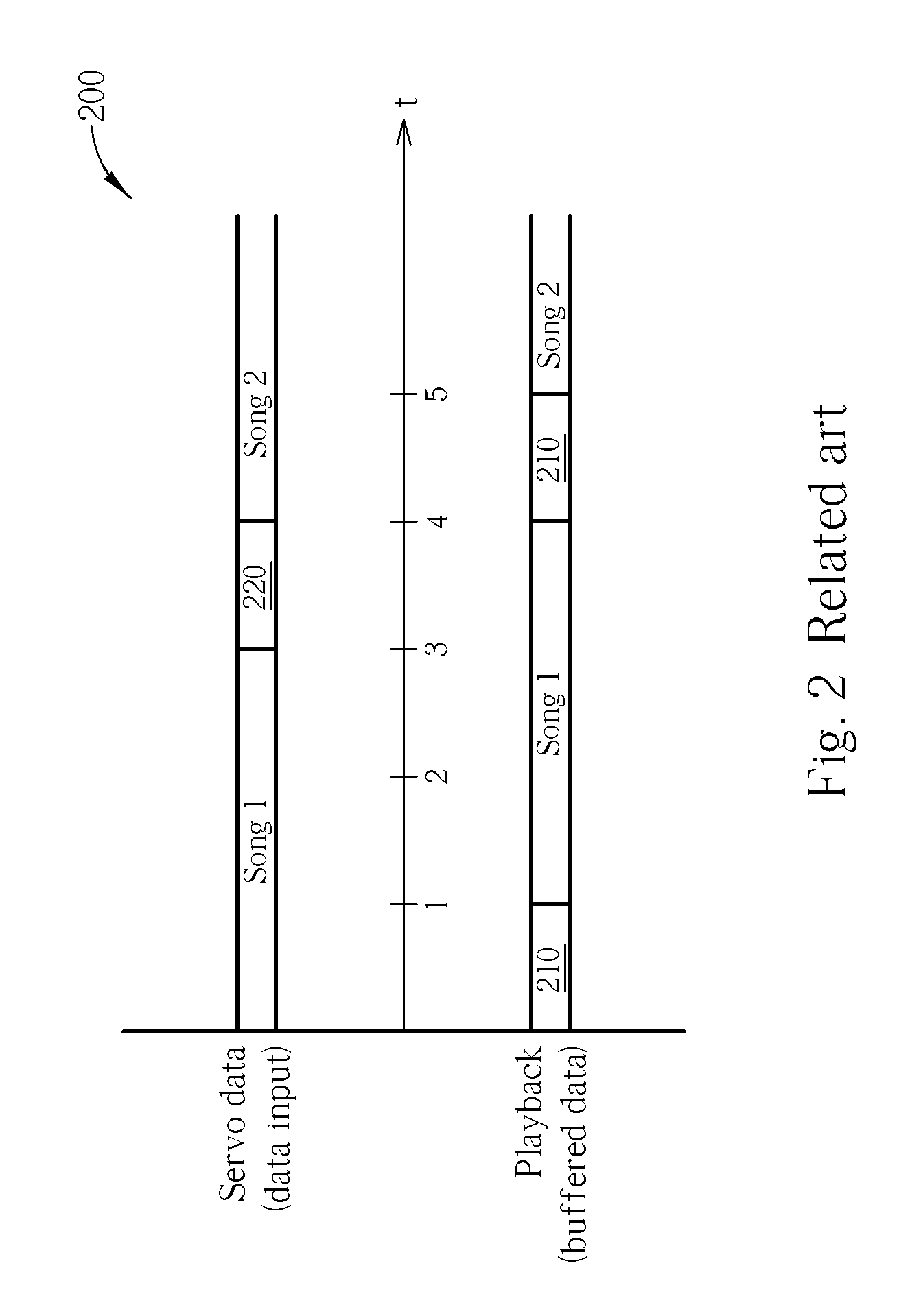
Playback (buffered data output) does not begin until an internal buffer capacity has been reached, resulting in a buffer delay 210 before streaming playback can start.

Method used


Image

  • Buffer control system for reducing buffer delay time between the playback of tracks and method thereof
  • Buffer control system for reducing buffer delay time between the playback of tracks and method thereof
  • Buffer control system for reducing buffer delay time between the playback of tracks and method thereof

Examples


Embodiment Construction

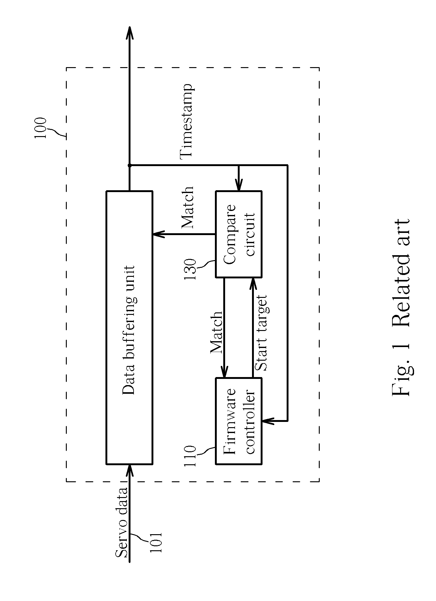
[0023]Because the related art firmware controller of the audio player in FIG. 1 handles both the end targeting process and the acquisition of upcoming tracks, it must wait for the completion of one process before it can begin the other. Current methods do not allow for the simultaneous operation of both processes by the firmware controller. The related art method burdens the firmware controller resources, and prohibits the firmware controller from acquiring the next track target at an earlier time, such as during the end targeting process. Invariably, this results in the buffer delay 210 experienced between the playback of tracks as described above.

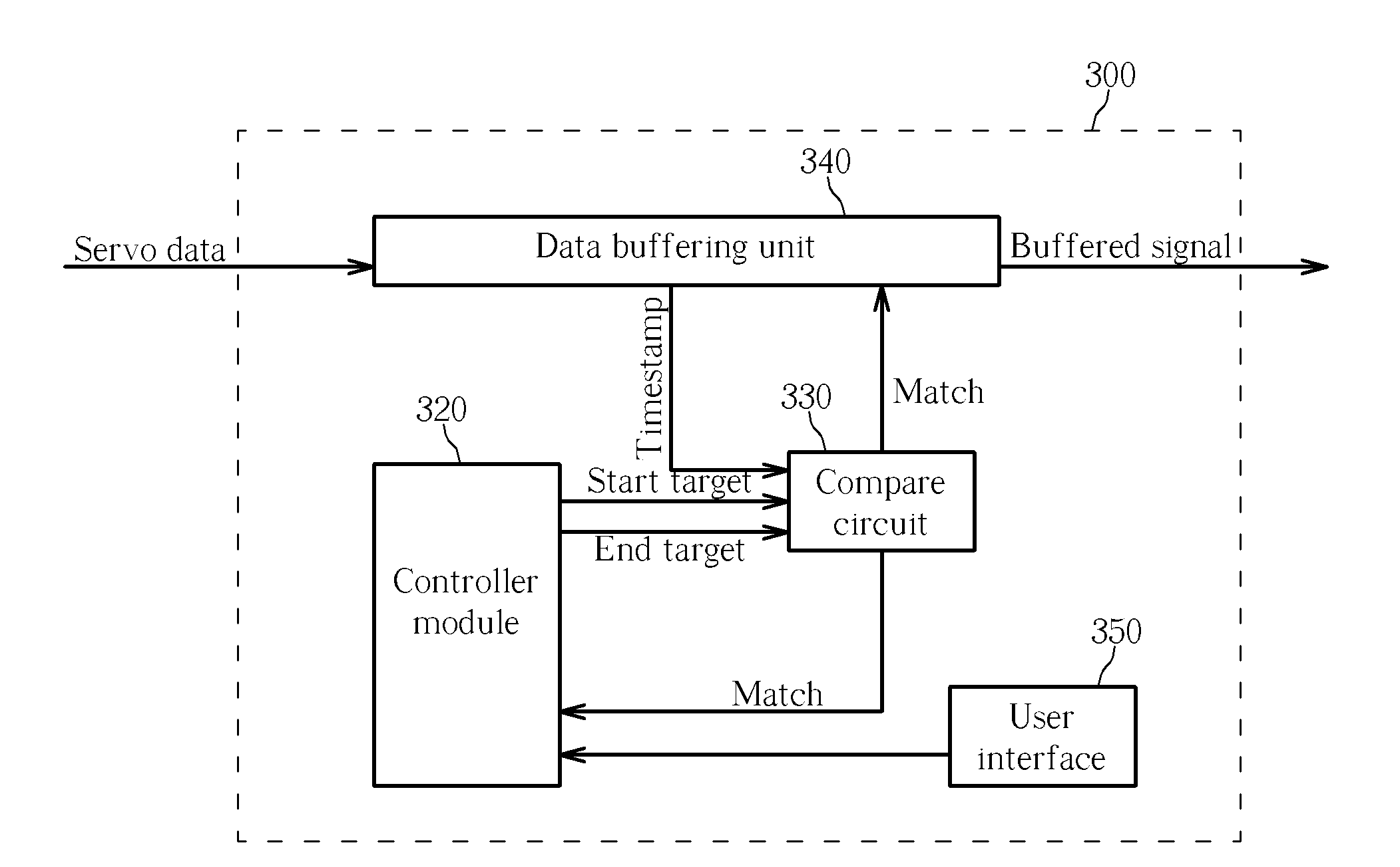
[0024]FIG. 3 is a diagram of a buffer control system for reducing buffer delay time between the playback of tracks according to a first exemplary embodiment of the present invention. The buffer control system 300 comprises a controller module 320, a compare circuit 330, a data buffering unit 340, and a user interface 350.

[0025]Operation o...


PUM

PropertyMeasurementUnit
delay timeaaaaaaaaaa
current capacityaaaaaaaaaa
timeaaaaaaaaaa

Abstract

A buffer control system for generating a buffered signal having reduced buffer delay time between playback of tracks includes a controller module for providing an end target and for selection of a servo data signal corresponding to a desired track; a compare circuit coupled to the servo data signal for comparing a timestamp of the servo data signal to the end target, and asserting an end match signal when the timestamp of the servo data signal matches the end target; and a data buffering unit for storing the servo data signal as stored data to fill a capacity of an internal memory, and streaming out the buffered signal from the stored data in the internal memory when the capacity has reached a predetermined level; wherein the controller module is for updating selection of the servo data signal according to a next desired track upon assertion of the end match signal.

Description

BACKGROUND OF THE INVENTION[0001]1. Field of the Invention[0002]The present invention relates to optical media players, and more particularly, to a buffer control system for reducing a buffer delay time occurring between the playback of tracks.[0003]2. Description of the Prior Art[0004]Optical media players continually rank amongst the more popular consumer electronics devices for audio / visual enthusiasts. The availability of various types of music and data formats provides a wide array of choices for a consumer to select from. Some of the more popular media player types include CD disc players, VCD players, DVD players, and MP3 audio players from solid state memory or CD disc format.[0005]One of the key features inherent in media players of these types is the ability to immediately select and play specific songs or segments. The data located in the storage medium is separated into tracks, with each individual track corresponding to a specific song or section. Tracks are further spa...

Claims


Application Information

Patent Timeline
Patent Type & Authority Patents(United States)
IPC IPC(8): G11B7/00
CPCG11B20/10527G11B27/105G11B2020/10768G11B2020/1287G11B2220/2537
Inventor CHEN, YEOW-CHYI
Owner AUTOCHIPS
Learn More