
Series electric-mechanical water pump system for engine cooling

a technology of water pump and engine, which is applied in the direction of engine cooling apparatus, mechanical apparatus, machines/engines, etc., to achieve the effects of reducing engine load, minimizing system parasitic loss, and improving vehicle fuel efficiency

Active Publication Date: 2012-06-12
FCA US
View PDF17 Cites 17 Cited by
  • Summary
  • Abstract
  • Description
  • Claims
  • Application Information

AI Technical Summary

Benefits of technology

This configuration reduces parasitic loss and improves total fuel efficiency by optimizing coolant flow and heat management, allowing the system to operate efficiently across various engine loads and temperatures.

Problems solved by technology

The lack of flow to the heater core keeps the heater core cool, when heat is not desired in the passenger compartment.

Method used


Image

  • Series electric-mechanical water pump system for engine cooling
  • Series electric-mechanical water pump system for engine cooling
  • Series electric-mechanical water pump system for engine cooling

Examples


Embodiment Construction

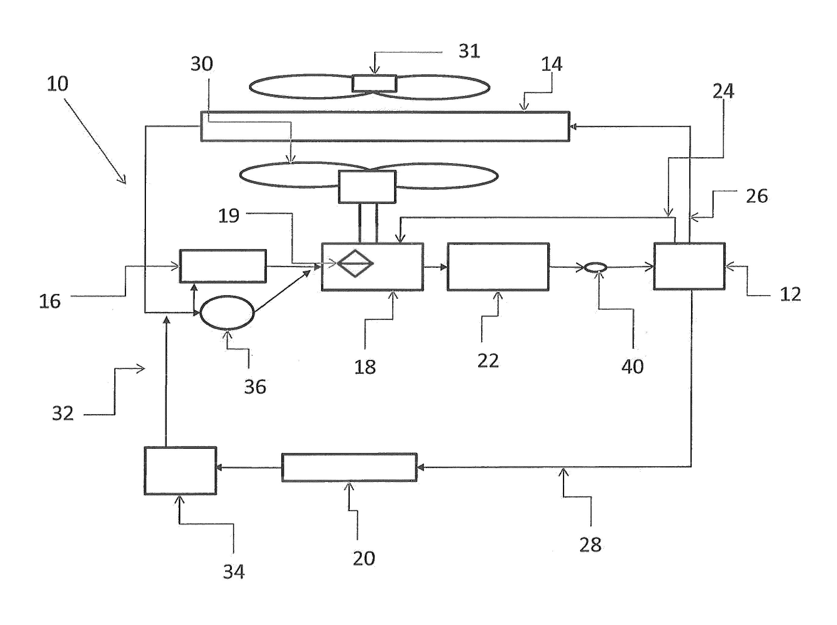
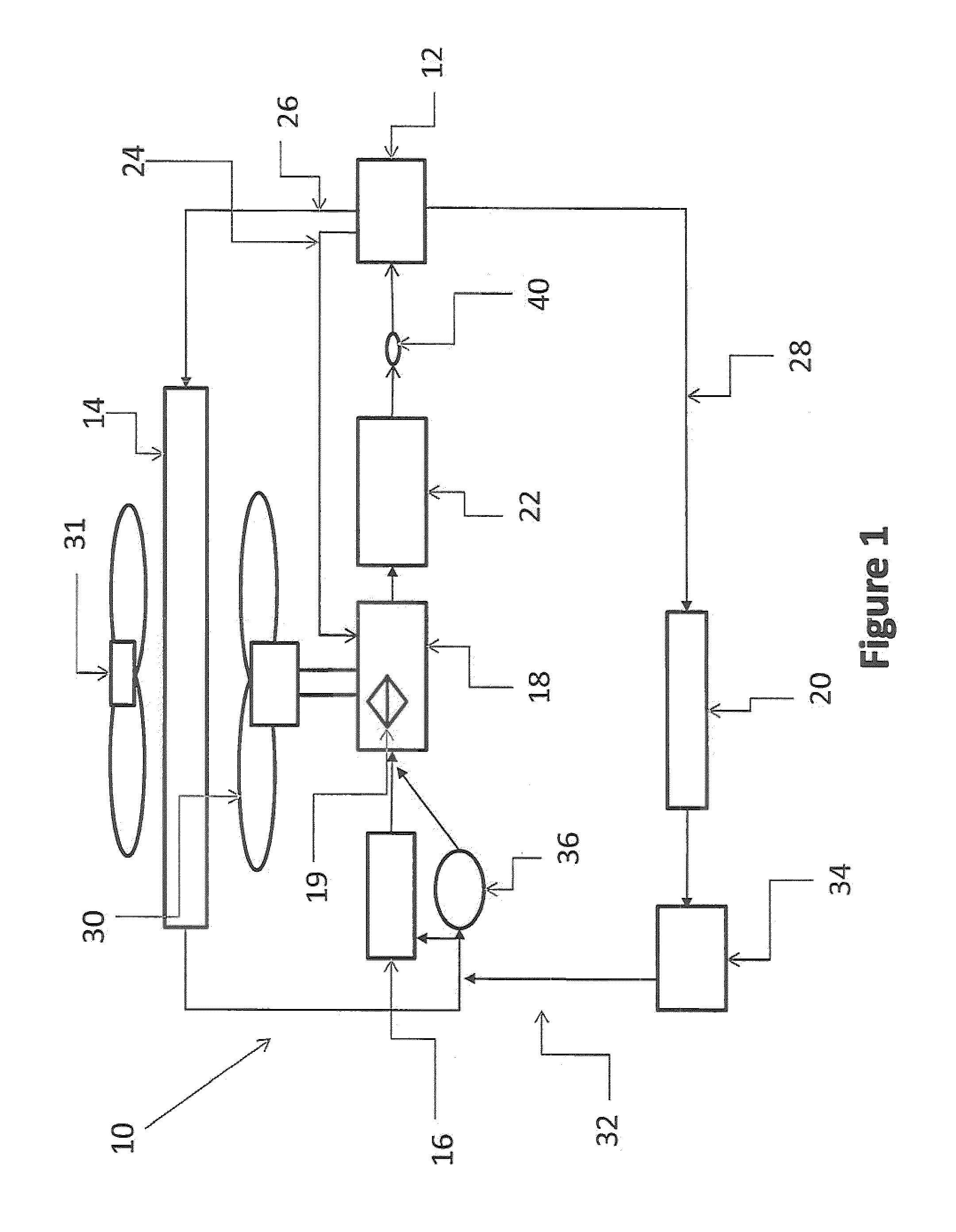
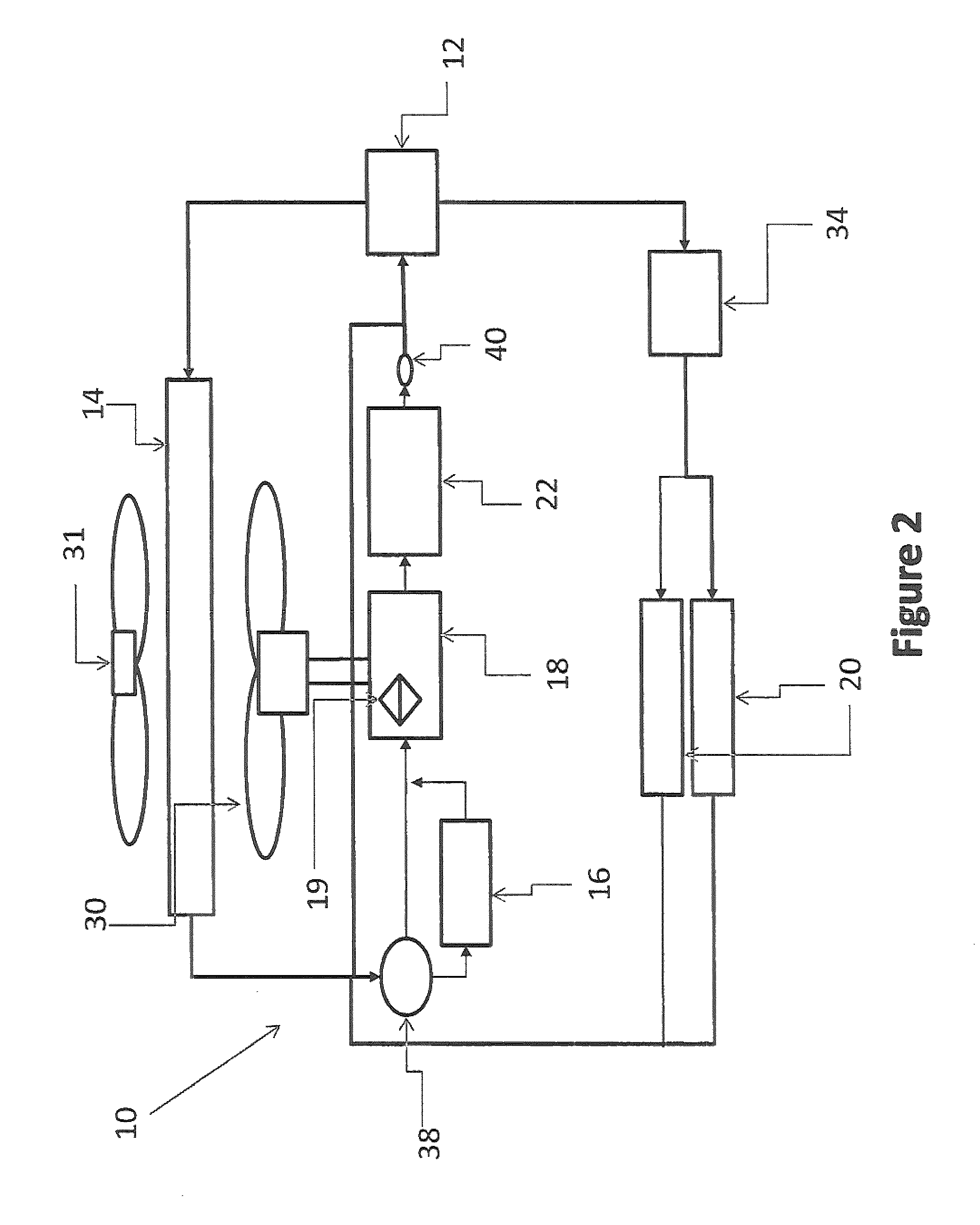
[0027]Referring now specifically to the drawings, an exemplary system is illustrated in FIG. 1 and is shown generally at reference numeral 10. FIG. 1 generally depicts the cooling system of an internal combustion vehicle. As illustrated, the system 10 generally comprises a thermostat 12, radiator 14, electric pump 16, mechanical pump 18, heater core 20, and engine 22.

[0028]Coolant flow through the system 10 is controlled by the thermostat 12, which is operatively mounted in a coolant flow control junction formed in the engine block (not shown). The thermostat 12 is operatively secured in the flow control junction by thermostat housing that is in turn secured by screws to a mounting pad fastened to or formed on the engine block. The thermostat controls the flow of the coolant through the system 10, and directs the flow of coolant depending upon the temperature of the coolant. The coolant is optionally directed along three ducts, which comprise a bypass hose 24, a supply hose 26, and ...


PUM


Abstract

A cooling system for an internal combustion engine of a motor vehicle having a rotating member and using coolant in a liquid cooling system, is provided that comprises a radiator for dissipating the heat from the coolant, an electric pump for pumping the coolant through the cooling system, a mechanical pump operatively connected to the rotating member for pumping coolant through the cooling system, and a clutch for disengaging the second pump for minimizing the parasitic loss of the system and improving total fuel economy of the vehicle.

Description

CROSS REFERENCE TO RELATED APPLICATIONS[0001]This application claims the benefit of U.S. Provisional Application 61 / 024,671 filed Jan. 30, 2008.FIELD OF THE INVENTION[0002]The present invention relates generally to a cooling system for internal combustion engines. The present invention more particularly relates to an engine cooling system wherein an electric water pump and mechanical water pump are arranged in series for cooling an internal combustion engine.[0003]Cooling systems for internal combustion engines typically contain a mechanical pump that is driven by a rotating member, such as a crankshaft, to pump water through the cooling system, a radiator, a mechanical fan, a thermostat, and a coolant that serves as a medium of heat transfer, such as ethylene glycol and corrosion inhibitors. The coolant circulates through the system to disperse the heat generated by the engine. The thermostat controls the flow of the coolant to the radiator by gradually allowing coolant flow at a p...

Claims


Application Information

Patent Timeline
Patent Type & Authority Patents(United States)
IPC IPC(8): F01P7/02
CPCF01P5/12F01P2005/105F01P2005/125
Inventor KLINE, RONALD F.LABOE, KEVIN J.VESPA, ANTONIO
Owner FCA US
Learn More