
Process for mounting a metal part in a composite material part

a composite material and metal part technology, applied in the direction of material gluing, lamination apparatus, fastening means, etc., can solve the problems affecting the performance of the assembly, and affecting so as to achieve long-lasting and sufficiently homogeneous performance, the effect of reducing the quality of the assembly

Active Publication Date: 2012-06-05
CAPAERO
View PDF9 Cites 2 Cited by
  • Summary
  • Abstract
  • Description
  • Claims
  • Application Information

AI Technical Summary

Benefits of technology

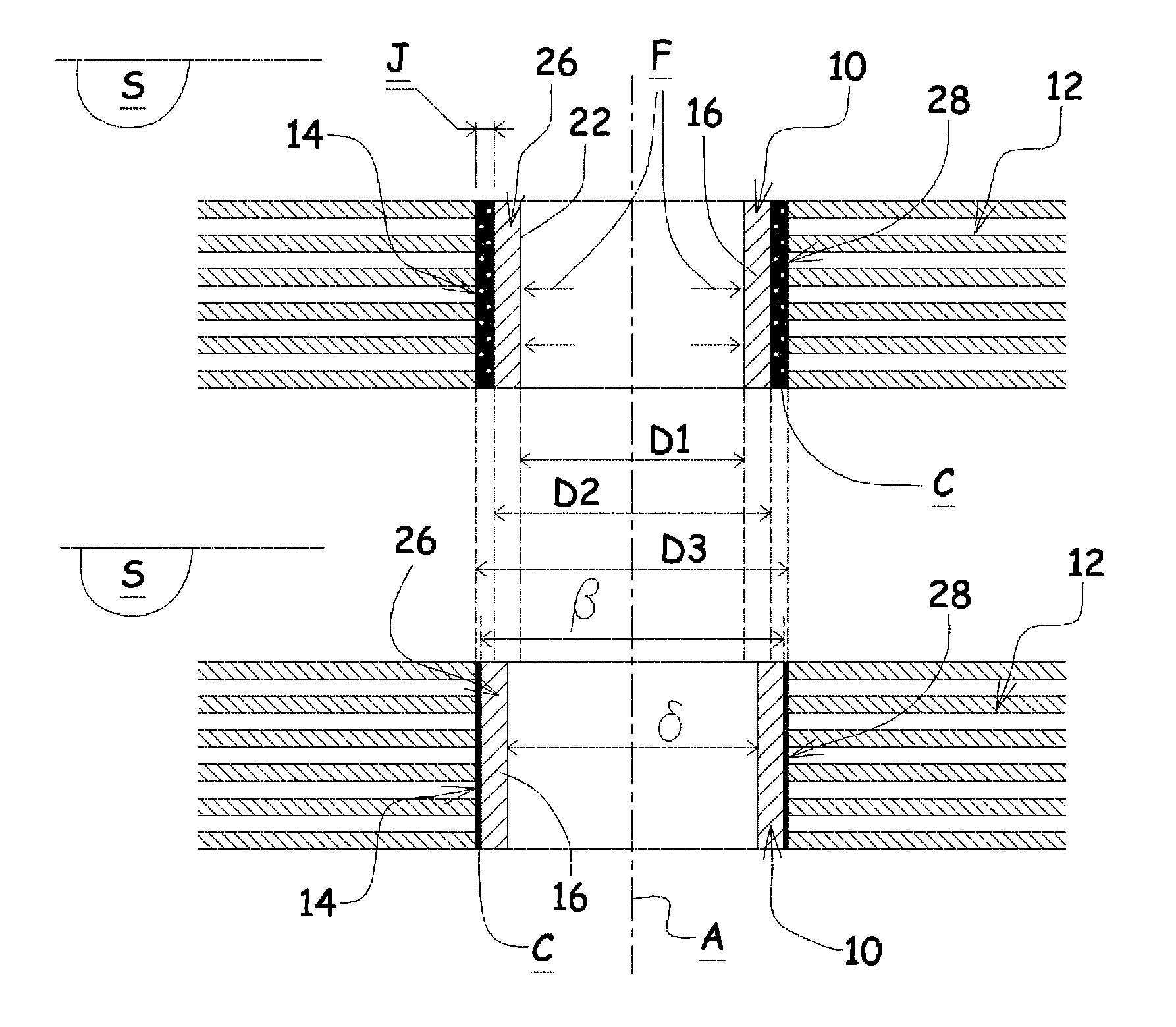
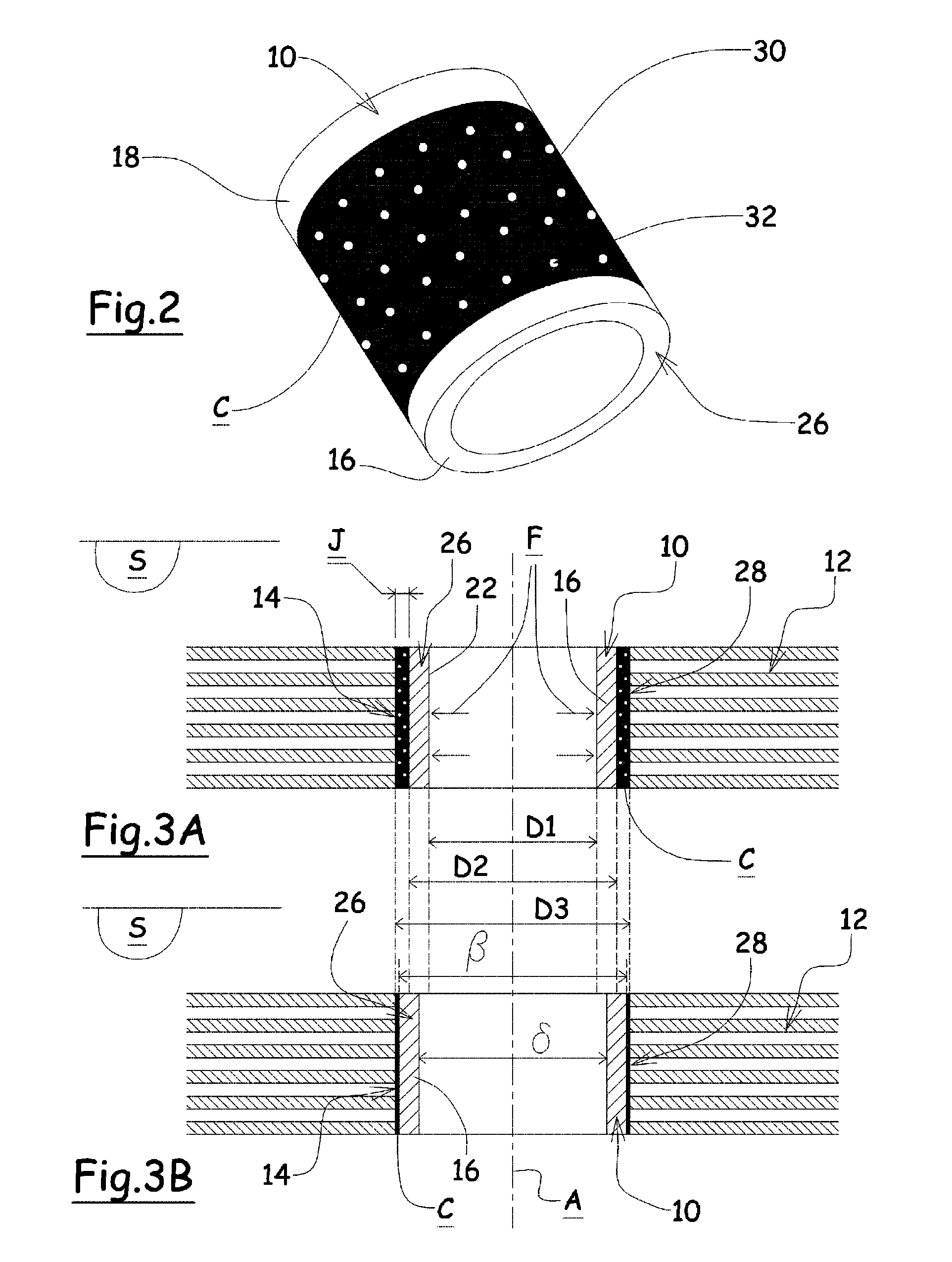
[0031]Thus, the invention opposes a preconceived idea according to which the creation of a connection between a metal part and a composite material part cannot use an expansion stage of said metal part in a housing of said composite material part without running the risk of deteriorating and reducing the quality of the assembly.

Problems solved by technology

Some of these sub-assemblies are subjected to significant mechanical stresses and to a large number of cycles of use over the life of an aircraft.
However, despite improvements made in the modeling of the properties of the materials and connections between parts and the processing of new materials, certain components and certain connections become damaged and should be replaced during maintenance operations, sometimes for repair work and sometimes for preventive maintenance in anticipation of fatigue in a material or wear and tear on a contact surface.
However, although they are widely used even now, these two processes of the prior art only make it possible to improve the mechanical characteristics and to extend the service life of a connection that comprises a hole that is made in a metal part.
The problem therefore arises of reinforcing and ensuring repair possibilities of the connections comprising a hole in a composite material part of an aircraft sub-assembly, including in a part that belongs to the structure of the aircraft and is able to be greatly stressed.
The sealing of a metal ring by means of an adhesive provides good resistance to detachment forces, but it cannot be considered as a mounting process that leads to long-lasting and sufficiently homogeneous performances.
In addition, the application of the adhesive on the outside wall of the ring just before its mounting and the bonding procedure are dependent on the operator, the manipulation being difficult to accomplish.
Another solution of the prior art calls for inserting the metal ring by co-curing during the production of the composite material part; this solution gives rise to costly and difficult implementation procedures.

Method used


Image

  • Process for mounting a metal part in a composite material part
  • Process for mounting a metal part in a composite material part
  • Process for mounting a metal part in a composite material part

Examples


Embodiment Construction

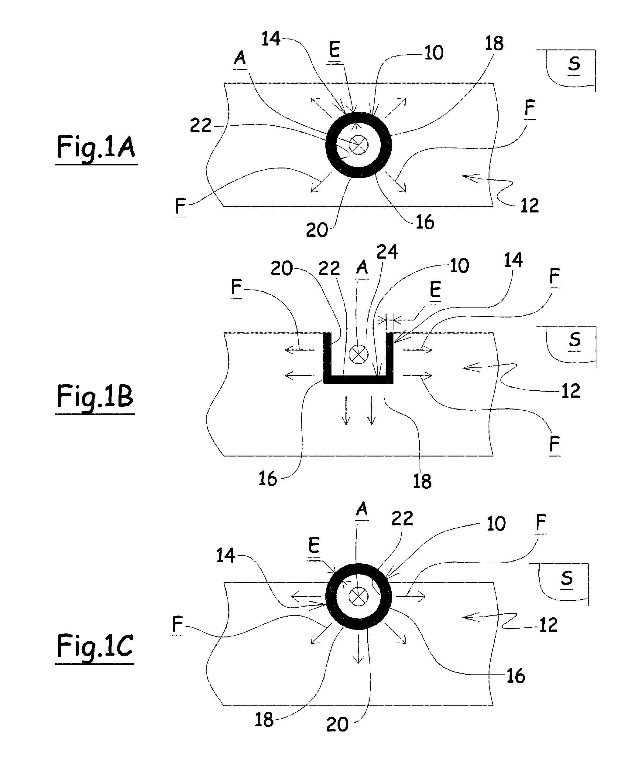
[0036]As illustrated in FIGS. 1A, 1B and 1C, the invention relates to a process for mounting a metal part 10, shown in a plane that is transversal to said figures, in a composite material part 12.

[0037]The process according to the invention is particularly designed to reinforce and to increase the service life of a connection of a composite material part that belongs to an aircraft sub-assembly.

[0038]More specifically, it gives rise to a process for mounting a metal part 10 in a receiving housing 14 that is provided for this purpose in a composite material part 12.

[0039]For this purpose, the receiving housing 14 has an inside profile 20 that is essentially a mirror image of the outside contour 18 of a portion 16 of the metal part 10, whereby said portion 16 comes into contact with the composite material.

[0040]According to the invention, the metal part 10 can comprise other portions that are connected to the portion 16 and that may or may not come into contact with the composite mate...


PUM

PropertyMeasurementUnit
thicknessaaaaaaaaaa
expansion forcesaaaaaaaaaa
shapeaaaaaaaaaa

Abstract

A process for mounting a metal part in a composite material part that belongs in particular to an aircraft subassembly, whereby the metal part includes at least one hollow portion and includes an inside wall that is identical in shape to its outside contour, whereby the inside wall and the outside contour are separated by the thickness of the portion, whereby the portion is pre-coated by glue and the composite material part includes at least one housing for receiving the inside profile that is a mirror image of the outside contour of the portion of the metal part, characterized in that the mounting process calls for ensuring an expansion of the inside wall of the portion that gives rise to an expansion of its outside contour and that determines the expansion forces applied by the portion against the wall of the housing.

Description

BACKGROUND OF THE INVENTION[0001]1. Field of the Invention[0002]This invention relates to a process for mounting a metal part in a composite material part that belongs in particular to an aircraft subassembly.[0003]2. Description of the Related Art[0004]Aircraft is defined as an airplane, a helicopter, any aerodyne craft that can operate within the Earth's atmosphere, or any space vehicle.[0005]An aircraft comprises numerous parts that form various sub-assemblies that are assembled with one another.[0006]These parts and these sub-assemblies are made integral with one another by means of various connections that are rigid or that allow certain degrees of freedom.[0007]Some of these sub-assemblies are subjected to significant mechanical stresses and to a large number of cycles of use over the life of an aircraft.[0008]For example, landing gear of an aircraft generally consists of numerous parts and sub-assemblies whose kinematics allows said gear to extend into / retract from a compartm...

Claims


Application Information

Patent Timeline
Patent Type & Authority Patents(United States)
IPC IPC(8): B29C65/02
CPCB29C65/5057B29C65/64B29C66/721B29C66/742B29C65/485B29C66/5326B29C65/8207B29K2105/06B29L2031/3076B29L2031/737F16B11/006F16B17/006B29K2305/00B29C66/1122B29C66/612
Inventor SAMENAYRE, JACQUESBRUEL, FRANCOIS
Owner CAPAERO
Learn More