
Golf club head

a golf club and swing technology, applied in the field of golf club heads, can solve the problems of inability to meet the needs of such users, players, especially those that are advanced, may feel discomfort, etc., and achieve the effects of reducing the swing feel reducing the height of the swing of the golf club, and reducing the lateral directionality of the flight of the hit ball

Active Publication Date: 2012-06-05
BRIDGESTONE SPORTS
View PDF58 Cites 163 Cited by
  • Summary
  • Abstract
  • Description
  • Claims
  • Application Information

AI Technical Summary

Benefits of technology

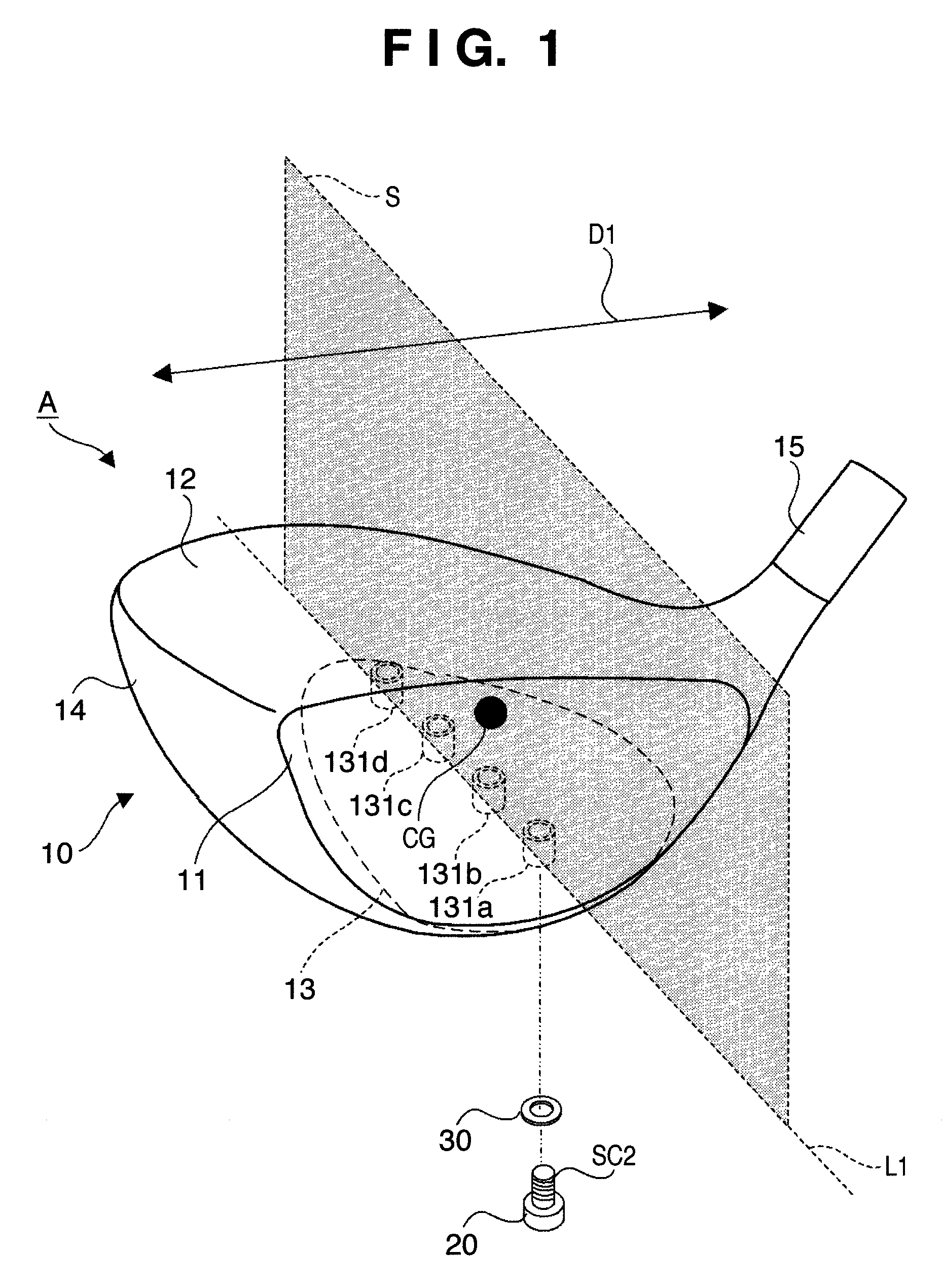
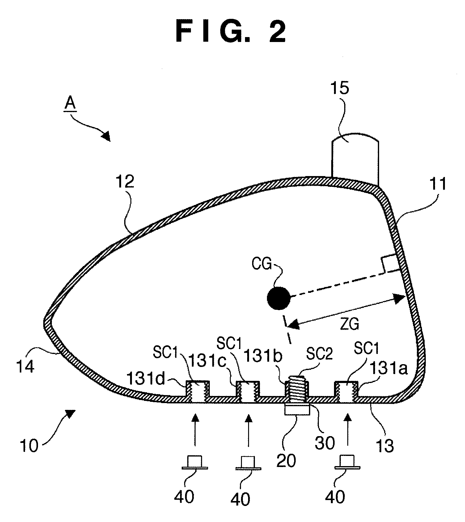
The present invention provides a golf club head with a movable weight member that can adjust the flight of the hit ball and change the swing feel of the golf club. The weight member can be fixed at multiple positions on the head body, which are located on a straight line and perpendicular to the toe-and-heel direction of the head body. This results in a more stable and accurate swing.

Problems solved by technology

However, some golfers may want to adjust only the height of ball flight.
If both the height and lateral directionality of flight of the hit ball change in accordance with a change in position of the weight member, it is not possible to satisfy such users' needs.
In addition, if a swing feel of a golf club largely changes in accordance with a change in position of the weight member, players, particularly those that are advanced, may feel a sense of discomfort.

Method used


Image

  • Golf club head
  • Golf club head
  • Golf club head

Examples


first embodiment

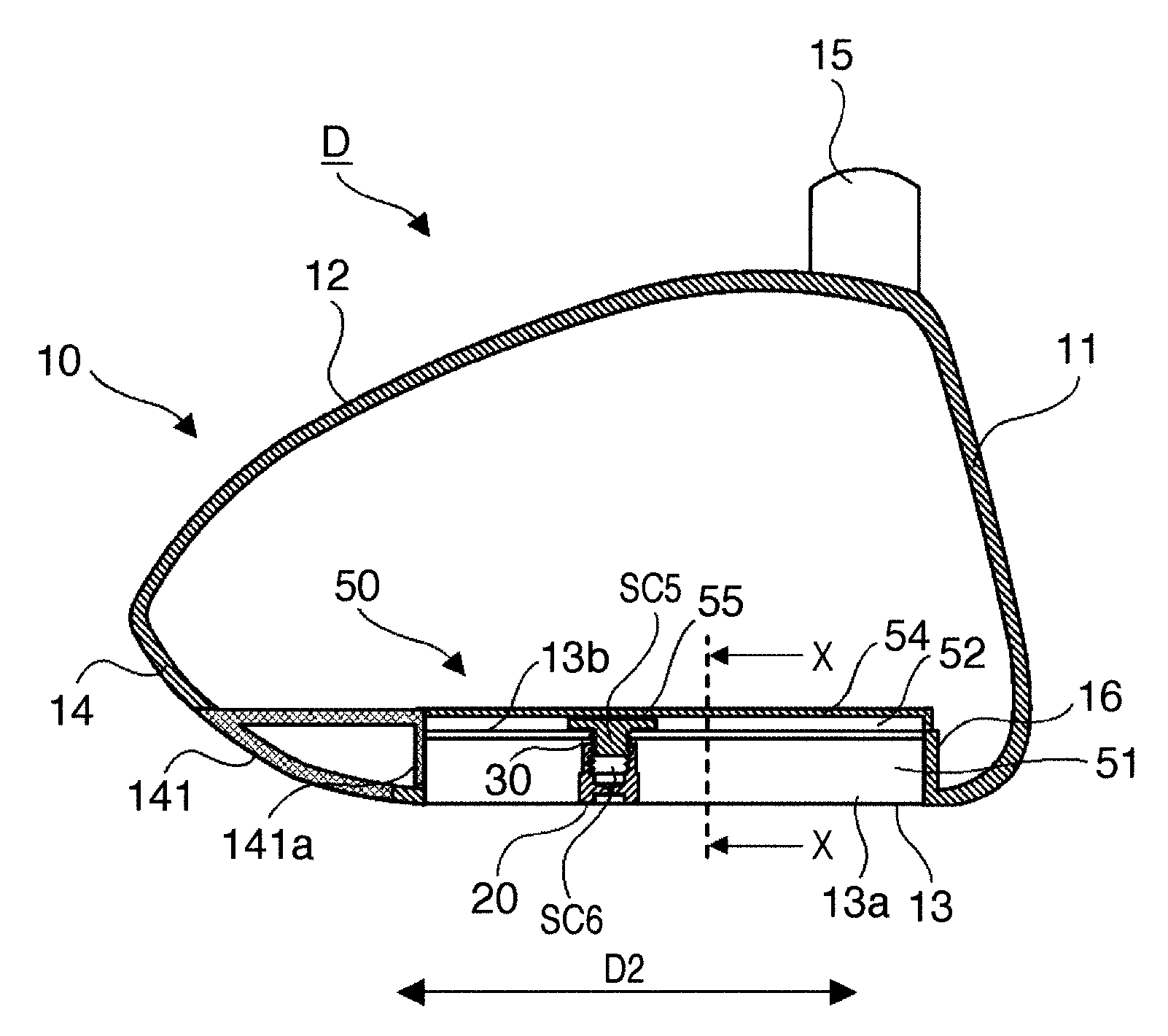
[0037]FIG. 4 is a sectional view of a golf club head B according to another embodiment of the present invention, taken along the same plane as in the sectional view of FIG. 2. The same components as in the golf club head A of the above-described first embodiment are denoted by the same reference numerals below, and a description thereof will not be repeated. Only components different from those of the golf club head A will be described.

[0038]In this embodiment, recesses 132a to 132d to accommodate a weight member 20 are provided in attachment portions 131a to 131d, respectively. The depth of each of the recesses 132a to 132d is set such that the lowest portion of the weight member 20 fixed to a head body 10 is positioned above the lowest portion of a sole portion 13.

[0039]With this arrangement, as shown in FIG. 4, the weight member 20 does not project from the sole portion 13. Accordingly, it is possible to prevent the weight member 20 from catching the ground upon hitting a ball.

[0...

second embodiment

[0041]In this embodiment, axial male screw portions SC3 are provided in respective attachment portions 131a to 131d, and a female screw hole SC4 which threadably engages with the male screw portion SC3 is provided in a weight member 20. Each of the attachment portions 131a to 131d also has an internal space to accommodate the weight member 20, so the weight member 20 does not project from a sole portion 13, as in the above-described

[0042]In this manner, the screw portion on the sole portion 13 side and that on the weight member 20 side may be a male screw and female screw, respectively, and vice versa.

[0043]In the above-described first to third embodiments, the weight member 20 can be fixed at a plurality of positions on the straight line L1 spaced apart from each other. However, the weight member 20 may be fixable at a give position on the straight line L1. With this arrangement, it is possible to more finely adjust the center-of-gravity position and center-of-gravity weight of the...


PUM


Abstract

A golf club head of this invention includes a head body, a weight member attached to the head body, and a fixing unit to fix the weight member at any one of a plurality of attachment positions of the head body. The plurality of attachment positions are located on a straight line included in a plane. The plane includes the center-of-gravity position of the head body without the weight member attached thereto and is perpendicular to the toe-and-heel direction of the head body.

Description

BACKGROUND OF THE INVENTION[0001]1. Field of the Invention[0002]The present invention relates to a golf club head.[0003]2. Description of the Related Art[0004]There have been proposed golf club heads in which golfers can change the position of a weight member attached to the golf club head in accordance with their preference. Japanese Patent Laid-Open Nos. 2001-137400, 2006-102235, and 2007-222257 disclose putter heads in which the position of the weight member can be changed. Japanese Utility Model Laid-Open No. 7-15067, Japanese Patent Laid-Open No. 11-9742, and Japanese Utility Model Registration No. 3127234 disclose wood type golf club heads in which the position of the weight member can be changed.[0005]When the position of the weight member is changed, the center-of-gravity position of the golf club head changes. In a wood type or utility type (hybrid type) golf club head, as the center-of-gravity position changes, the height or lateral directionality of flight of a hit ball c...

Claims


Application Information

Patent Timeline
Patent Type & Authority Patents(United States)
IPC IPC(8): A63B53/04A63B53/06A63B102/32
CPCA63B53/0466A63B2053/0433A63B2209/00A63B2053/0491A63B53/0433A63B60/02A63B53/04
Inventor BAN, WATARU
Owner BRIDGESTONE SPORTS
Learn More