Golf club head
- Summary
- Abstract
- Description
- Claims
- Application Information
AI Technical Summary
Benefits of technology
Problems solved by technology
Method used
Image
Examples
first embodiment
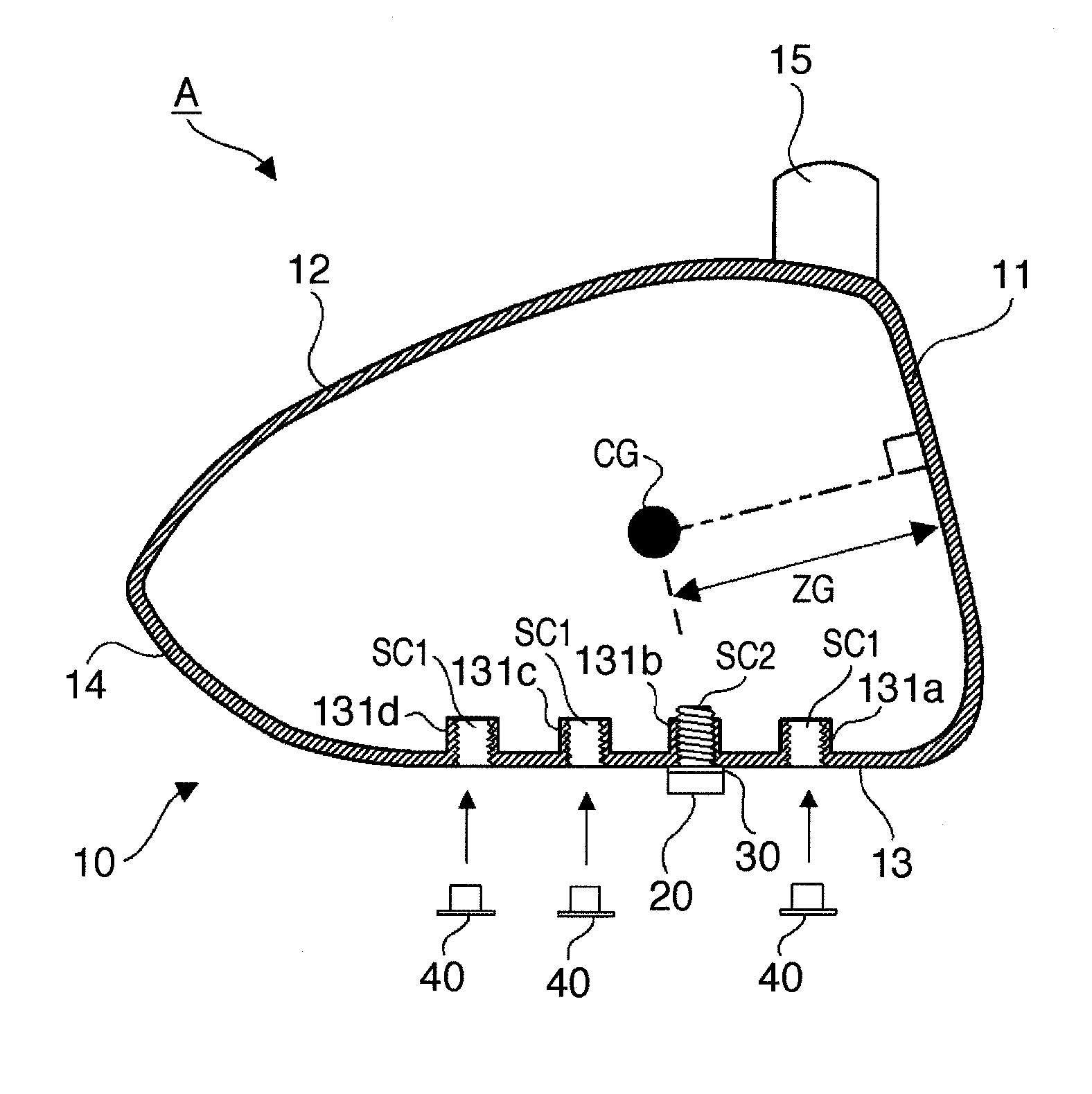
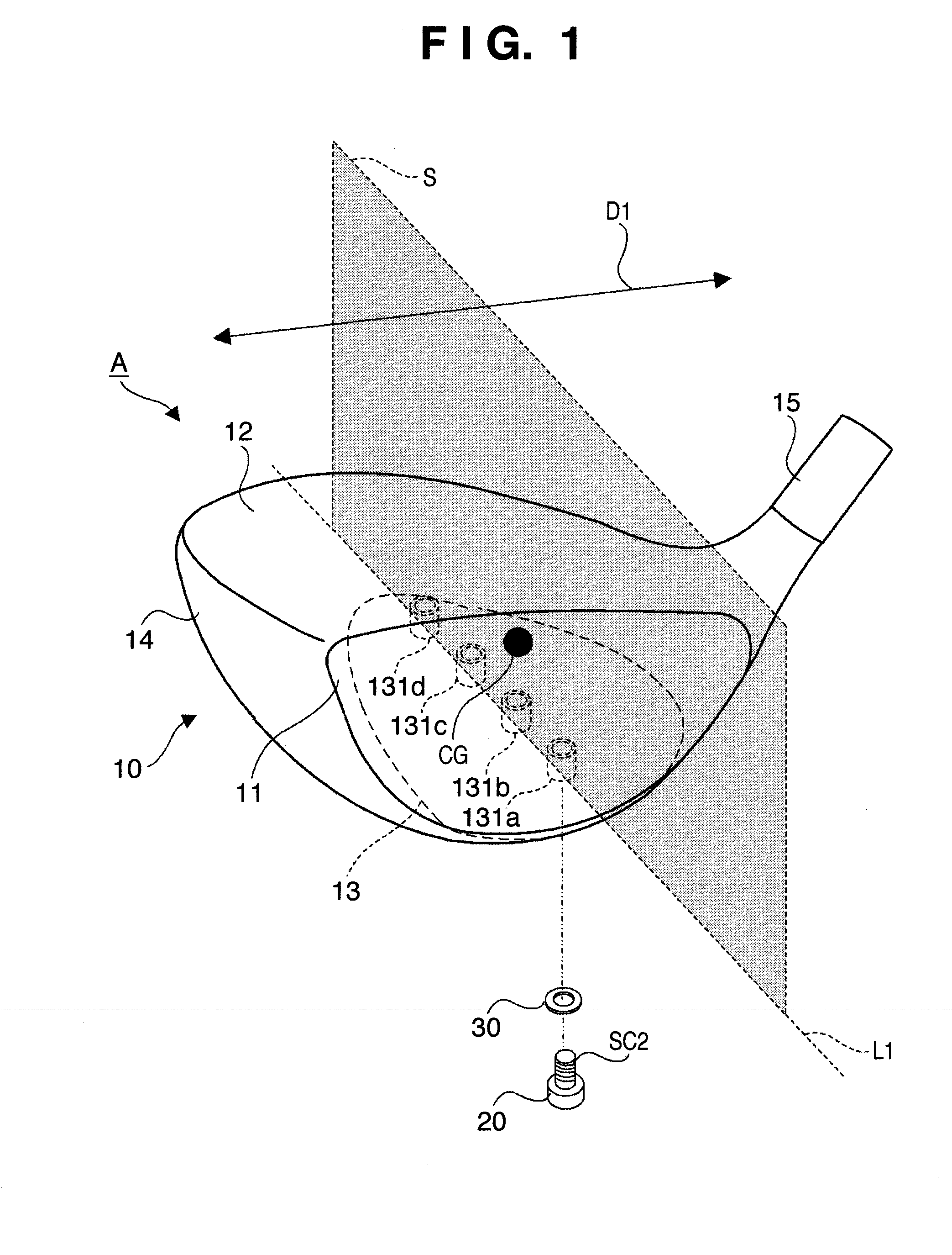
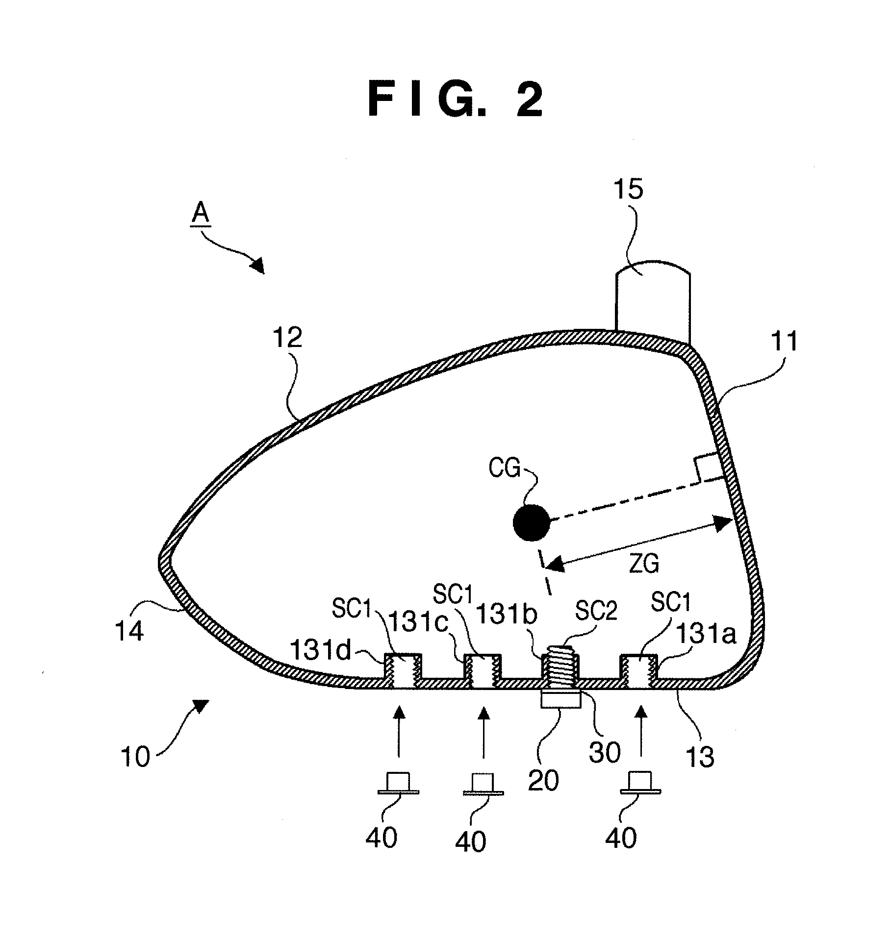
[0018]FIG. 1 is a perspective view of a golf club head A, and particularly of a sole portion 13 according to one embodiment of the present invention. FIG. 2 is a sectional view of the golf club head A taken along a plane S in FIG. 1 when seen from the toe side of the golf club head A.
[0019]The golf club head A includes a head body 10 and a weight member 20. The head body 10 is a hollow body, and its circumferential wall constitutes a face portion 11 forming a golf ball hitting surface, a crown portion 12 forming the top surface of the golf club head A, the sole portion 13 forming the bottom surface of the golf club head A, and a side portion 14 forming the toe-side, heel-side, and back-side side surfaces of the golf club head A. A hosel portion 15 to which a shaft is to be attached is also provided in the head body 10.
[0020]Although the golf club head A is a golf club head for a driver, the present invention is applicable to wood type golf club heads including a fairway wood and the...
second embodiment
[0037]FIG. 4 is a sectional view of a golf club head B according to another embodiment of the present invention, taken along the same plane as in the sectional view of FIG. 2. The same components as in the golf club head A of the above-described first embodiment are denoted by the same reference numerals below, and a description thereof will not be repeated. Only components different from those of the golf club head A will be described.
[0038]In this embodiment, recesses 132a to 132d to accommodate a weight member 20 are provided in attachment portions 131a to 131d, respectively. The depth of each of the recesses 132a to 132d is set such that the lowest portion of the weight member 20 fixed to a head body 10 is positioned above the lowest portion of a sole portion 13.
[0039]With this arrangement, as shown in FIG. 4, the weight member 20 does not project from the sole portion 13. Accordingly, it is possible to prevent the weight member 20 from catching the ground upon hitting a ball.
third embodiment
[0040]FIG. 5 is a sectional view of a golf club head C according to still another embodiment of the present invention, taken along the same plane as in the sectional view of FIG. 2. The same components as in the golf club head A of the above-described first embodiment are denoted by the same reference numerals below, and a description thereof will not be repeated. Only components different from those of the golf club head A will be described.
[0041]In this embodiment, axial male screw portions SC3 are provided in respective attachment portions 131a to 131d, and a female screw hole SC4 which threadably engages with the male screw portion SC3 is provided in a weight member 20. Each of the attachment portions 131a to 131d also has an internal space to accommodate the weight member 20, so the weight member 20 does not project from a sole portion 13, as in the above-described second embodiment.
[0042]In this manner, the screw portion on the sole portion 13 side and that on the weight membe...
PUM
 Abstract
Description
Claims
Application Information
 - R&D
- Intellectual Property
- Life Sciences
- Materials
- Tech Scout
- Unparalleled Data Quality
- Higher Quality Content
- 60% Fewer Hallucinations
Browse by: Latest US Patents, China's latest patents, Technical Efficacy Thesaurus, Application Domain, Technology Topic, Popular Technical Reports.
© 2025 PatSnap. All rights reserved.Legal|Privacy policy|Modern Slavery Act Transparency Statement|Sitemap|About US| Contact US: help@patsnap.com


