
Mechanical control device especially for controlling a high-voltage or medium-voltage disconnector

a technology of mechanical control device and high-voltage disconnector, which is applied in the direction of gearing, switch power arrangement, hoisting equipment, etc., can solve the problems of limiting the possibility of providing torque limiter means elsewhere than on the transmission shaft, and the drawback of being heavy and bulky, and achieves the effect of light weigh

Active Publication Date: 2012-06-05
ALSTOM TECH LTD
View PDF11 Cites 7 Cited by
  • Summary
  • Abstract
  • Description
  • Claims
  • Application Information

AI Technical Summary

Benefits of technology

[0014]A particular object of the invention is to provide a simple, economic, and efficient solution to these problems that avoids the above-mentioned drawbacks.
[0015]In particular the invention provides a mechanical control device for controlling an apparatus, in particular for controlling electrical switchgear, that is relatively compact and relatively light in weight.
[0016]It also provides a mechanical control device in which the transmission ratio between a rotary driving member driven by a motor unit and a rotary driven member intended to drive coupling means is constant or varies only slightly, so that means for limiting the torque transmitted to the driven member can be provided between the motor unit and the driving member, in particular in the vicinity of the motor unit, in order to minimize the overall size and the mass of the torque limiter means.

Problems solved by technology

However, such means have the drawback of being heavy and bulky, which is necessary because they are mounted on the transmission shaft and because of the high torque transmitted by the shaft.
Now, in a manner that is inherent to Geneva wheel mechanisms, the torque transmission ratio between the auxiliary shaft and the transmission shaft varies between a zero value and a maximum value during each phase of driving the transmission shaft in rotation, which limits the possibility of providing torque limiter means elsewhere than on the transmission shaft.

Method used


Image

  • Mechanical control device especially for controlling a high-voltage or medium-voltage disconnector
  • Mechanical control device especially for controlling a high-voltage or medium-voltage disconnector
  • Mechanical control device especially for controlling a high-voltage or medium-voltage disconnector

Examples


Embodiment Construction

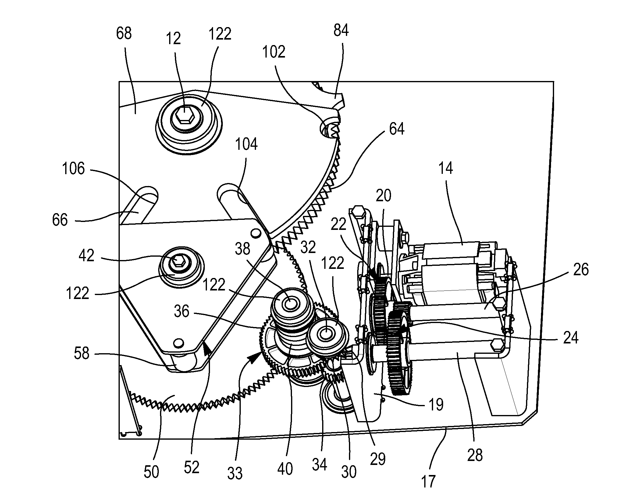
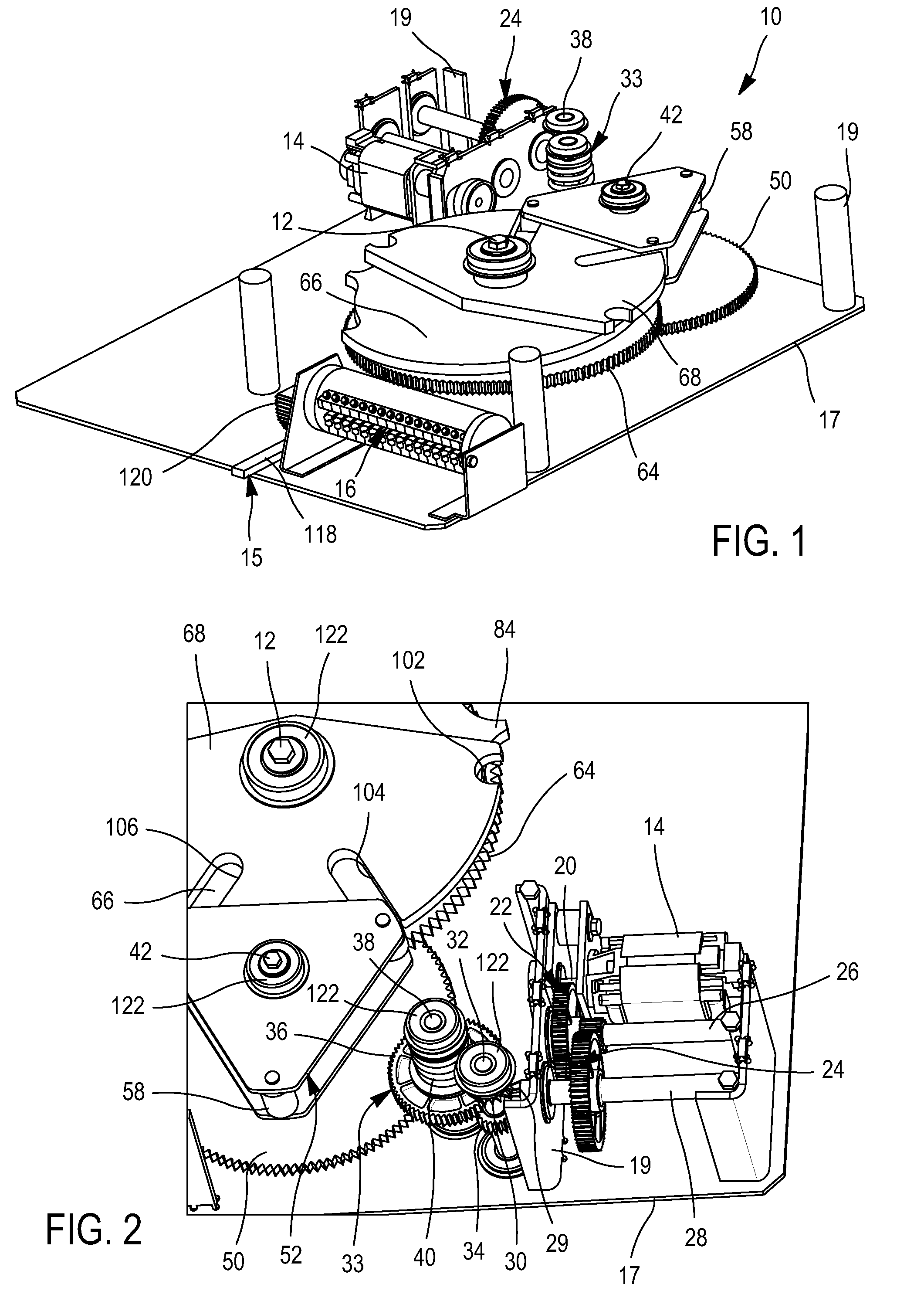
[0072]FIG. 1 represents a mechanical device 10 for controlling a disconnector (not shown) with three switching positions for high-voltage or medium-voltage circuits.

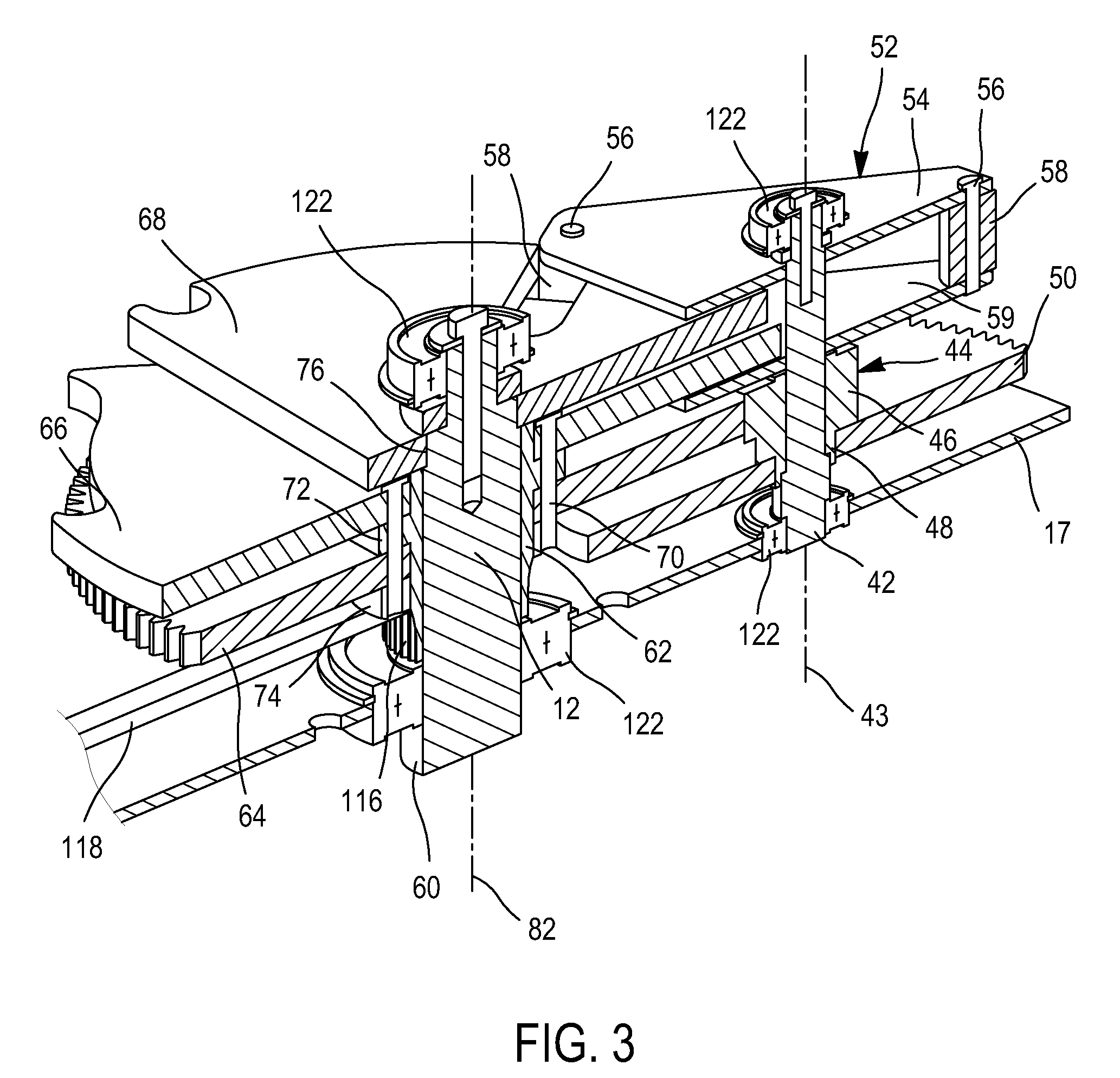
[0073]The device 10 includes a transmission shaft 12 adapted to be coupled to the movable contact of a disconnector of the above-mentioned type, an electric motor 14, means for transmitting power from said electric motor 14 to said transmission shaft 12, means 15 for indicating the angular position of said transmission shaft 12 to auxiliary switches 16, in particular for controlling the electric motor and for signaling said angular position of the transmission shaft 12, and a chassis plate 17 on which the main components of the device are mounted.

[0074]The device 10 further includes a top chassis plate, which is not shown in the figures in order to expose the internal components of the device. This top plate is fixed to uprights 19 connected to the chassis plate 17 and contributes to supporting certain components of the ...


PUM


Abstract

A control device, including a transmission shaft adapted to be coupled to an apparatus to be controlled, a driving disk mounted on said transmission shaft to rotate thereon and driven in rotation by a motor unit, a driven disk constrained to rotate with said transmission shaft, and a rotary member carrying at least one indexing means which, due to rotation of said rotary member, can be simultaneously engaged into two respective slots of said two disks for said transmission shaft to be driven in rotation, and can be disengaged from one of said slots for said transmission shaft to be locked against rotation.

Description

CROSS REFERENCE TO RELATED APPLICATIONS or PRIORITY CLAIM[0001]This application claims priority of French Patent Application No. 08 58927, filed Dec. 22, 2008.TECHNICAL FIELD[0002]The present invention relates to the field of mechanical control devices for electrical switchgear, in particular for disconnectors for high-voltage or medium-voltage circuits, and relates more generally to the field of mechanical control devices of the type comprising means for driving a transmission shaft in rotation and means for locking that shaft in a discrete series of predetermined angular positions.[0003]High-voltage and medium-voltage disconnectors are used to isolate a portion of a live electrical network, such as a high-voltage line, an electrical transformer, or a portion of an electrical substation, for example, so that an operative can access it safely.[0004]These disconnectors include a contactor movable between a position for opening an electrical circuit and a position for closing the elec...

Claims


Application Information

Patent Timeline
Patent Type & Authority Patents(United States)
IPC IPC(8): B23Q16/02
CPCF16H27/06H01H3/26H01H3/44H01H31/003Y10T74/19005Y10T74/19879Y10T74/1418H01H9/16H01H33/42
Inventor VON ALLMEN, PETERZEUGIN, MARTIN
Owner ALSTOM TECH LTD
Learn More