
Cyclonic separation device comprising two cyclones linked by an optimised pipe unit

a technology of optimised pipe unit and cyclone, which is applied in the direction of dispersed particle separation, separation process, reverse direction vortex, etc., can solve the problems of device size, significant head loss, and progressive clogging

Active Publication Date: 2019-02-05
ROLLS ROYCE NUCLEAR FIELD SERVICES FRANCE
View PDF10 Cites 0 Cited by
  • Summary
  • Abstract
  • Description
  • Claims
  • Application Information

AI Technical Summary

Benefits of technology

The aim of the invention is to provide a simple, cheap and effective way to solve these problems. This solution can help avoid the issues that previously existed.

Problems solved by technology

This results however in a considerable size of the device.
This moreover makes it necessary to provide ducting means that are complex and of great length, likely to induce significant head loss.
The drawback of such a grid however resides in its progressive clogging, as the device is used.

Method used


Image

  • Cyclonic separation device comprising two cyclones linked by an optimised pipe unit
  • Cyclonic separation device comprising two cyclones linked by an optimised pipe unit
  • Cyclonic separation device comprising two cyclones linked by an optimised pipe unit

Examples


Embodiment Construction

[0010]The aim of the invention is notably to provide a simple, economic and efficient solution to these problems, making it possible to avoid at least in part the aforementioned drawbacks.

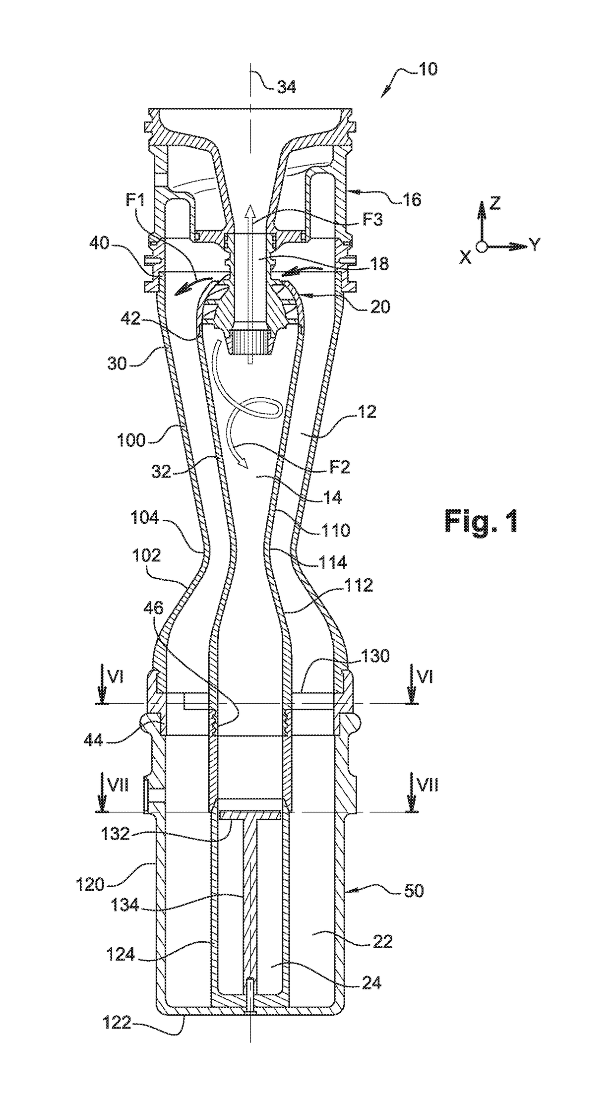
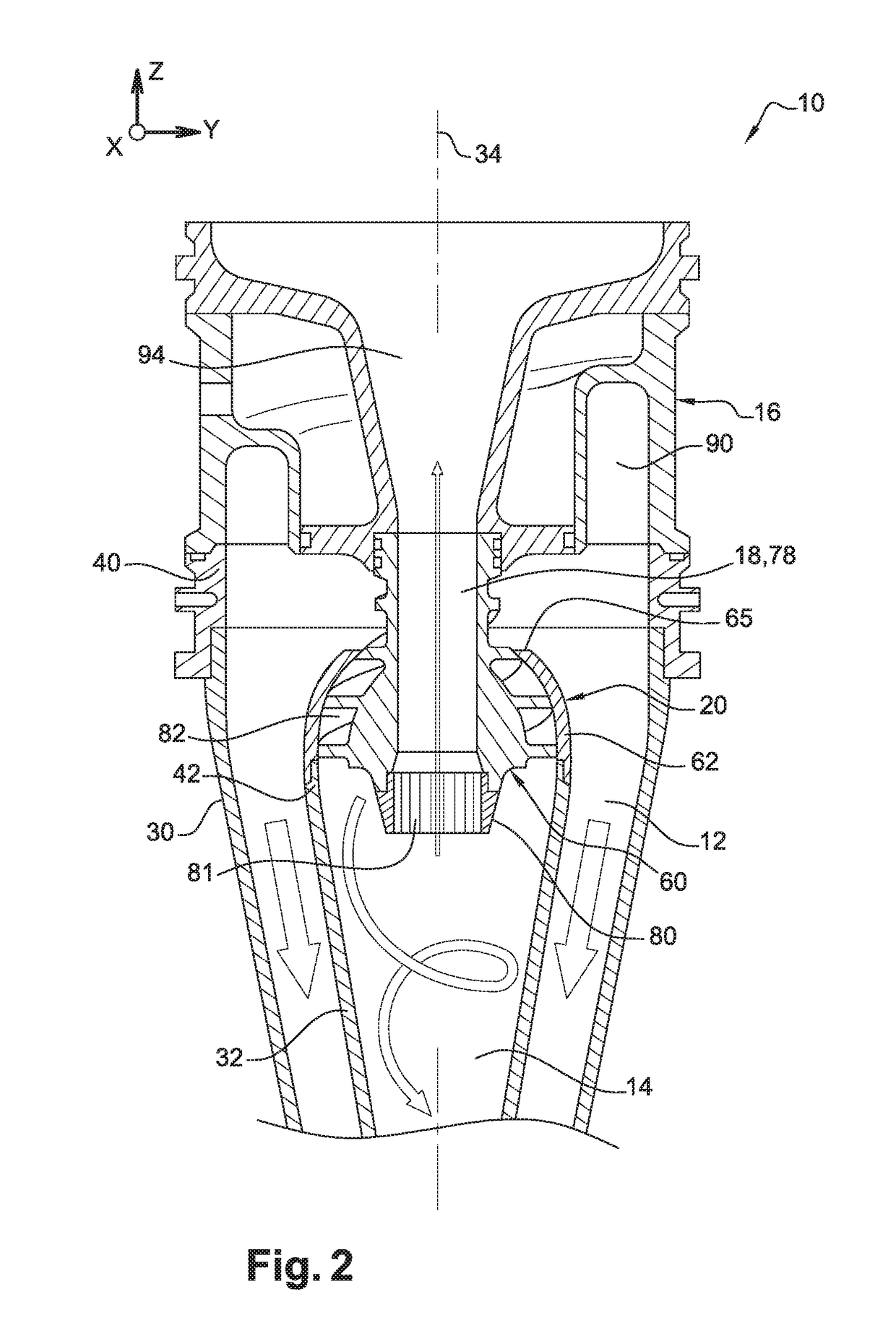
[0011]The invention proposes to this end a device for the cyclonic separation of solid particles contained in a fluid, for example a gas, including:[0012]a primary cyclone chamber;[0013]a secondary cyclone chamber;[0014]at least one inlet channel for fluid loaded with solid particles, opening into the primary cyclone chamber;[0015]at least one outlet channel for fluid cleaned of the solid particles, into which opens the secondary cyclone chamber; and[0016]a ducting unit that connects the primary cyclone chamber to the secondary cyclone chamber, and which is surrounded by the primary cyclone chamber.

[0017]According to the invention, the ducting unit includes:[0018]a core forming a limit of the secondary cyclone chamber, the core having an outer surface provided with at least one helical groove havin...


PUM

PropertyMeasurementUnit
helical shapeaaaaaaaaaa
forceaaaaaaaaaa
particle sizeaaaaaaaaaa

Abstract

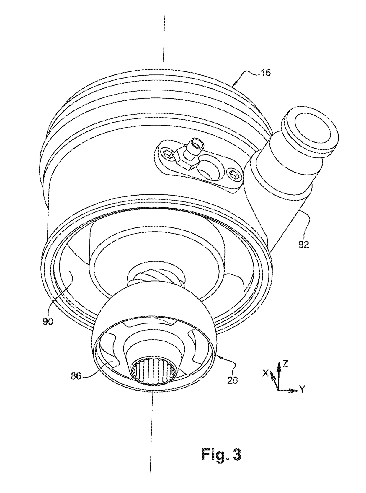
A device for the cyclonic separation of solid particles contained in a fluid, comprising a primary cyclone chamber, a secondary cyclone chamber, an inlet channel for fluid loaded with solid particles opening into the primary cyclone chamber, an outlet channel for fluid cleaned of the solid particles connected to the secondary cyclone chamber, and a ducting unit connecting the primary cyclone chamber to the secondary cyclone chamber and surrounded by the primary cyclone chamber. The ducting unit comprises a core delimiting the secondary cyclone chamber and having at least one helical groove having a bottom which diverges away from an axis of the secondary cyclone chamber in a direction towards the latter, and a cap covering a part of the core in such a way as to delimit, with the groove, a channel connecting the primary cyclone chamber to the secondary cyclone chamber.

Description

TECHNICAL FIELD[0001]The present invention pertains to the field of cyclonic separation of solid particles contained in a fluid, notably a gas, and more particularly relates to a device for same, comprising a primary cyclone chamber, a secondary cyclone chamber, at least one inlet channel for fluid loaded with solid particles opening into the primary cyclone chamber, at least one outlet channel for fluid cleaned of the solid particles connected to the secondary cyclone chamber, and a ducting unit connecting the primary cyclone chamber to the secondary cyclone chamber.STATE OF THE PRIOR ART[0002]Such a device operates by the rapid rotation of a fluid in order to separate therefrom the fine solid particles that are initially mixed therein. The separation results from the centrifugal force that tends to displace the solid particles to an outer wall. The friction of these particles along this wall in fact induces a reduction of the kinetic energy of said particles, resulting in their fa...

Claims


Application Information

Patent Timeline
Patent Type & Authority Patents(United States)
IPC IPC(8): B01D45/12B04C5/103B04C5/04B01D45/16B04C5/26B04C5/107B04C5/13
CPCB04C5/26B01D45/12B01D45/16B04C5/13B04C5/103B04C5/107B04C5/04
Inventor JEHANNO, JACKYPILISI, FRANCK
Owner ROLLS ROYCE NUCLEAR FIELD SERVICES FRANCE
Learn More