
Method for Temporarily Connecting Two Parts Together, such as Two Stages of a Space Launcher, and Assembly Including Two Temporarily Connected Parts

a technology of two parts and temporary connection, applied in the field of temporary connection between two parts, can solve the problems of high cost, unusable extra mass, and difficult use of composite materials, and achieve the effect of simple, economic and efficien

Active Publication Date: 2014-02-13
ARIANEGRP SAS
View PDF8 Cites 1 Cited by
  • Summary
  • Abstract
  • Description
  • Claims
  • Application Information

AI Technical Summary

Benefits of technology

The goal of this invention is to offer a practical, cheap, and effective solution to overcome these issues. The objective is to avoid or reduce the drawbacks associated with existing methods.

Problems solved by technology

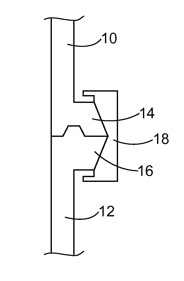
This type of connection has the drawback to require a mutual contact between radial flanges on the one hand, and between these flanges and the strap on the other hand.
The presence of these flanges induces an undesirable extra mass.
Moreover, the contact between the flanges and the strap requires careful control of friction between these elements as well as great geometric accuracy in making the same, which induces high costs and makes composite materials difficult to use.
That is the reason why elements involved in connections of this type are made of metal, which induces additional costs because of the relatively high mass of these elements.
Moreover, this makes such elements difficult to use when the cylindrical walls 10 and 12 are of composite material.
Because of the contact between the three flanges, this type of connection has drawbacks similar to that of the first type of connection in controlling the friction between the flanges and in geometric accuracy in making these flanges.
This type of connection also makes composite materials difficult to use.
This type of connection further has the drawback to require a complex assembly.

Method used


Image

  • Method for Temporarily Connecting Two Parts Together, such as Two Stages of a Space Launcher, and Assembly Including Two Temporarily Connected Parts
  • Method for Temporarily Connecting Two Parts Together, such as Two Stages of a Space Launcher, and Assembly Including Two Temporarily Connected Parts

Examples


Embodiment Construction

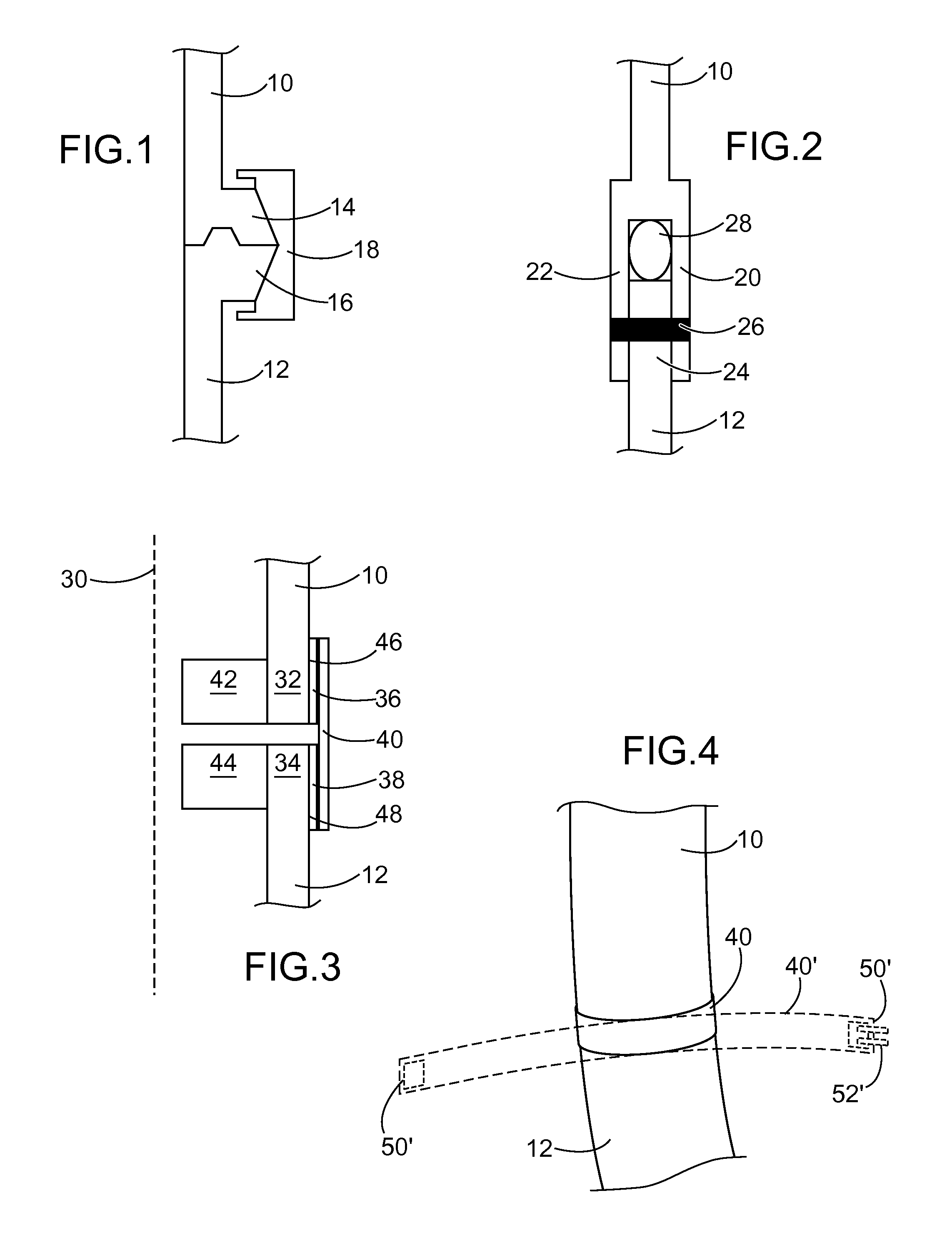
[0081]FIGS. 3 and 4 generally illustrate a temporary structural connection between two consecutive stages of a space launcher.

[0082]More precisely, FIG. 3 represents a connection area between two respective structural walls 10, 12 of these two stages, these walls having generally a revolution symmetry about a longitudinal axis 30 of these stages and being made of a composite material.

[0083]Such a structural connection is mainly intended to the transmission, between the aforesaid stages, of tensile strains parallel to the longitudinal axis 30, but also to a lesser extent, of shear strains.

[0084]Each of the structural walls 10, 12 of these stages includes a respective end part 32, 34 the external surface of which is covered with a corresponding layer of adhesive 36, 38 which circumferentially extends about the axis 30 as an annular strip.

[0085]In the particular example described in FIG. 3, the adhesive is a rigid curable adhesive based on an epoxy resin, marketed by the Henkel Company...


PUM


Abstract

A method for making a temporary connection between two parts (10, 12), comprising the following successive steps:placing a connecting element (40, 40′) into an operating position wherein said connecting element surrounds the assembly formed by said parts and is subjected to an internal deformation strain;locking the position of said connecting element by stress-keeping means (52′) with controlled relief;connecting said connecting element (40, 40′) to each part (10, 12) by attaching means (36, 38);and wherein said internal deformation stress is at a sufficient level to enable the connecting element (40, 40′) to be unsecured from said parts (10, 12) by extending to a rest position, during a release control of said stress-keeping means (52′).

Description

TECHNICAL FIELD[0001]The present invention relates to the field of temporary connections between two parts.[0002]It was initially developed for an application to the structural connection between two stages of a space launcher, but it can also be applied to the connection between a payload and a space launcher, satellite, probe, missile or airplane, or even to the connection of any type of parts which must be controllably separated.[0003]The invention relates in particular to a method for temporarily connecting two parts, as well as an assembly of two parts temporarily connected by a connecting element.STATE OF PRIOR ART[0004]Space launchers comprise several stages intended to be successively separated during a flight. Before they are separated, these stages are connected in pairs by structural connections, that is able to transmit mechanical strains between these stages, in particular tensile strains, and capable of being controllably ruptured to cause a separation of these stages....

Claims


Application Information

Patent Timeline
Patent Type & Authority Applications(United States)
IPC IPC(8): F16B11/00
CPCF16B11/006B64G1/641Y10T403/477
Inventor VEILLERAUD, FREDERIC
Owner ARIANEGRP SAS
Learn More