
Cross-layer optimization for scalable video multicast over IEEE 802.11 wireless local area networks

a video multicast and wireless local area network technology, applied in the field of video content, can solve the problems of high error rate in wireless networks, inability to guarantee the reliability of users without excellent receiving conditions, and approach that does not yield optimal system performance for video delivery, so as to achieve optimal overall video quality and optimal overall video quality. the effect of all the receivers

Active Publication Date: 2012-05-29
INTERDIGITAL VC HLDG INC
View PDF17 Cites 24 Cited by
  • Summary
  • Abstract
  • Description
  • Claims
  • Application Information

AI Technical Summary

Benefits of technology

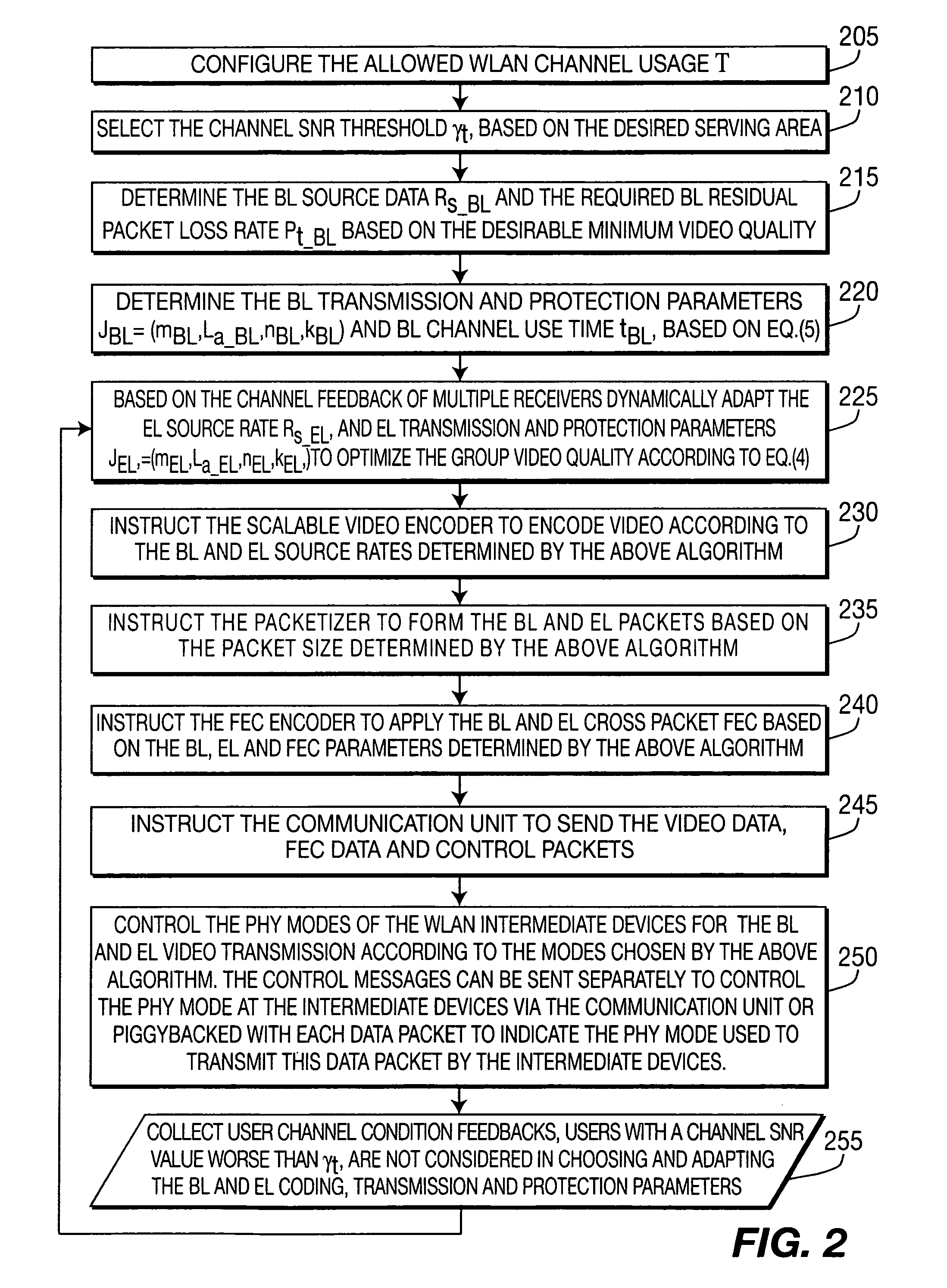
[0008]The present invention is based on an adaptive cross layer optimization method and system for scalable video multicast in IEEE 802.11 WLANs. The present invention, therefore, controls and adapts the various coding, transmission and protection mechanisms available in different network protocol layers, including modulation and channel coding mode in physical layer (PHY mode), application layer forward error correction (FEC) overhead, packetization, and scalable video coding rate, to achieve the optimal overall video quality of all the receivers of the multicast video session in the desired / target service area. Furthermore, different cross-layer transmission and protection parameters are applied to a base layer and an enhancement layer of the scalable video according to the importance of the layers (base and enhancement). The method and system of the present invention are capable of dynamically adapting to the varying user topology and channel conditions of multiple users.
[0009]A system and method for transmitting video signals to a plurality of receivers in a multicast session, including controlling and adapting coding, transmission and protection schemes of a plurality of layers of a network protocol stack are described. The system and method of the present invention achieve optimal overall video quality for receivers in a multicast session in a target service area.

Problems solved by technology

The error rate is usually high in wireless networks.
For multicast, the IEEE 802.11 wireless link layer does not perform retransmission of lost packets.
The required reliability cannot, therefore, be guaranteed to the users without excellent receiving conditions.
This layered approach does not yield an optimal system performance for video delivery.
This strategy is, however, not applicable to multicast.
Second, the IEEE 802.11 link layer does not perform retransmission of lost multicast data frames.
It is not straightforward to optimize the bandwidth allocation when the channel bandwidth is adjustable for different PHY modes.

Method used


Image

  • Cross-layer optimization for scalable video multicast over IEEE 802.11 wireless local area networks
  • Cross-layer optimization for scalable video multicast over IEEE 802.11 wireless local area networks
  • Cross-layer optimization for scalable video multicast over IEEE 802.11 wireless local area networks

Examples


Embodiment Construction

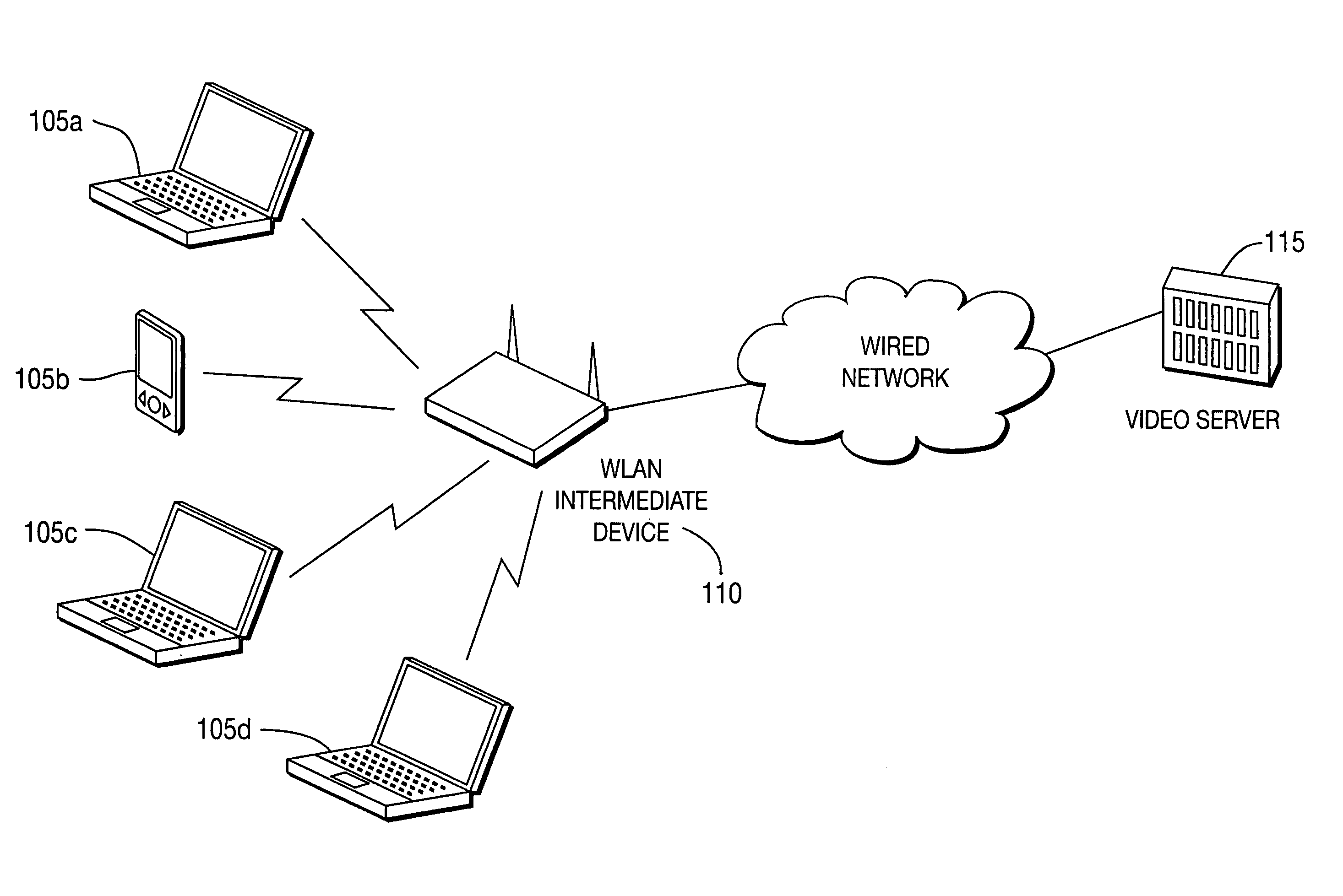
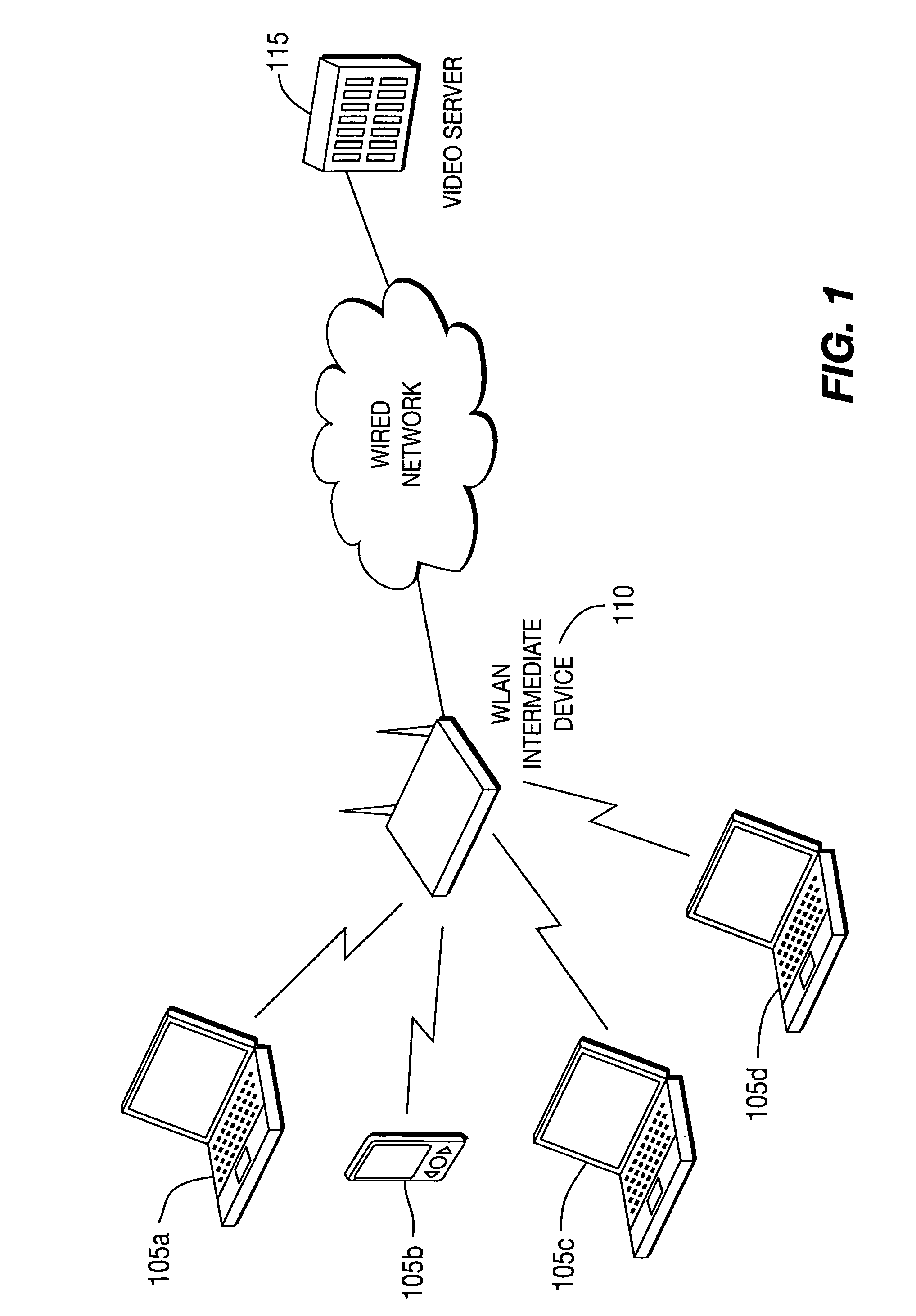
[0020]Referring now to FIG. 1, a typical network system considered in the context of the present invention is shown. The wireless devices 105a, 105b, 105c, 105d are connected to a video multicast server through IEEE 802.11 wireless intermediate devices 110 (such as wireless access points or wireless routers) and a high-speed wired access network (e.g. Ethernet). Wireless devices include wireless mobile devices such as, but not limited to, mobile phones, cell phones, personal digital assistants (PDAs), laptops, mobile terminals and any other wireless devices that are or can be mobile / wireless. The video server 115 transmits one or more video programs in multicast over the high-speed wired network to the wireless intermediate devices 110. The intermediate devices distribute the video to the wireless devices in multicast over the IEEE 802.11 wireless local area networks (WLANs). The users of the wireless devices 105a-105d can view one or more video programs. The network topology depict...


PUM


Abstract

A system and method for transmitting video signals to a plurality of receivers in a multicast session, including controlling and adapting coding, transmission and protection schemes of a plurality of layers of a network protocol stack are described.

Description

[0001]This application claims the benefit, under 35 U.S.C. §365 of International Application PCT / US2005 / 030756, filed Aug. 30, 2005, which was published in accordance with PCT Article 21(2) on Jun. 28, 2007 in English.FIELD OF THE INVENTION[0002]The present invention relates to video content that is multicast over wireless local area networks (WLANs) and more specifically to the improvement of video quality by optimizing distribution for targeted users by adjusting error control strategies across multiple layers of the protocol stack.BACKGROUND OF THE INVENTION[0003]Video multicast over IEEE 802.11 wireless local area networks (WLANs) enables the distribution of live or pre-recorded video to multiple receivers efficiently, for example, the distribution of TV programs or location specific video information in hotspots such as airport, café, hotel and shopping mall, etc. Users can watch their favorite TV programs on mobile devices while browsing the Internet. Other examples include ex...

Claims


Application Information

Patent Timeline
Patent Type & Authority Patents(United States)
IPC IPC(8): H04N7/12H04N19/89H04N21/6405
CPCH04L1/0007H04N19/34H04L1/0014H04N21/21H04N21/23H04N21/234327H04N21/2662H04N21/43637H04N21/440227H04N21/6131H04N21/6405H04N19/115H04N19/154H04N19/166H04N19/187H04N19/89H04L1/0009H04L2001/0093
Inventor HAN, LIQIAOLIU, HANGRAMASWAMY, KUMAR
Owner INTERDIGITAL VC HLDG INC
Learn More