
Cooling system for hybrid vehicles

a hybrid vehicle and cooling system technology, applied in hybrid vehicles, lighting and heating apparatus, semiconductor/solid-state device details, etc., can solve the problems of increasing the number of components, the configuration of the battery is not designed and the ability to cool the motor control unit and the dc-dc converter. to achieve the effect of reducing production costs, simplifying the structure and reducing the number of components

Active Publication Date: 2012-05-29
HANON SYST
View PDF7 Cites 39 Cited by
  • Summary
  • Abstract
  • Description
  • Claims
  • Application Information

AI Technical Summary

Benefits of technology

The present invention provides a cooling system for hybrid vehicles that can simultaneously cool a battery, a motor control unit, and a DC-DC converter all together by using a single unified cooling arrangement. This system can minimize the number of components required, while enjoying a simplified structure and reduced production costs. The system includes a blower for drawing air from the passenger compartment, an introduction duct for introducing the air into the battery storage room to cool the battery, two supply ducts for supplying the air to the DC-DC converter and the motor control unit, and an air distributor means for distributing the air to both ducts.

Problems solved by technology

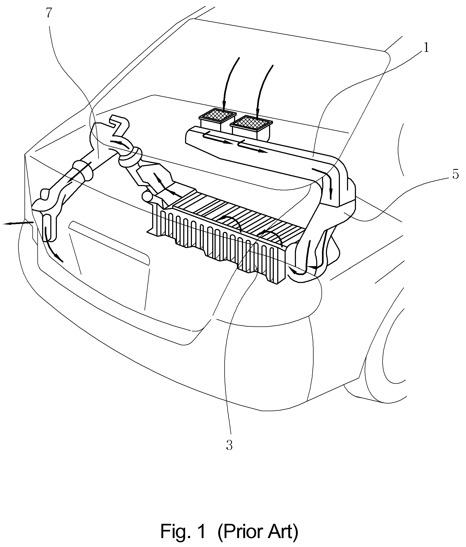
One drawback of such a conventional cooling system is that it is configured to cool nothing but the battery and has no ability to cool the motor control unit and the DC-DC converter.
This poses a problem in that separate cooling devices need to be provided to cool the motor control unit and the DC-DC converter.
This is problematic in that the number of components is increased as well and hence the cooling system becomes structurally complex with an attendant increase in production costs.

Method used


Image

  • Cooling system for hybrid vehicles
  • Cooling system for hybrid vehicles
  • Cooling system for hybrid vehicles

Examples


Embodiment Construction

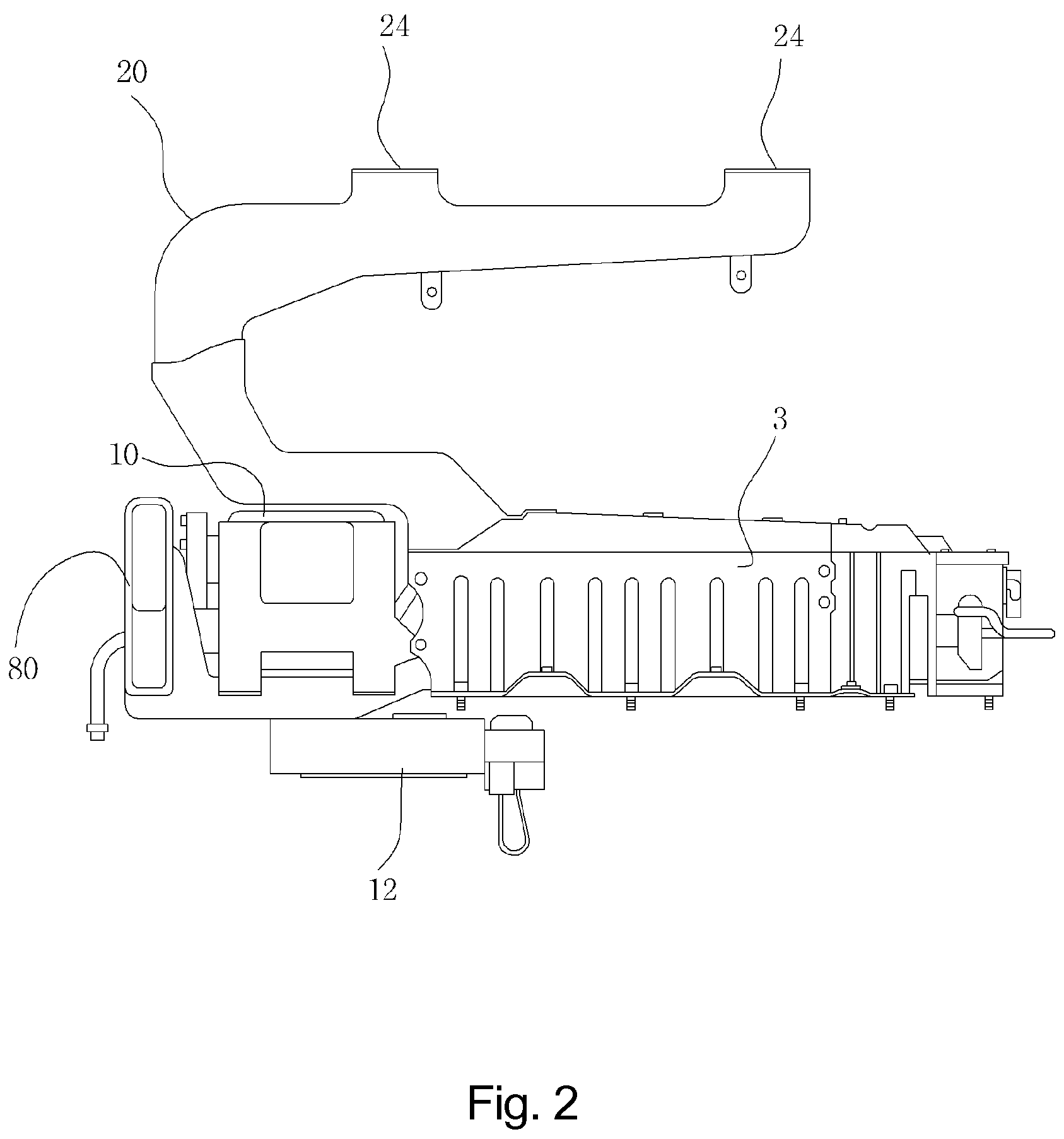
[0025]Hereinafter, a preferred embodiment of a cooling system for hybrid vehicles in accordance with the present invention will be described in detail with reference to the accompanying drawings. The same parts or components as those of the prior art cooling system will be designated and described with like reference numerals.

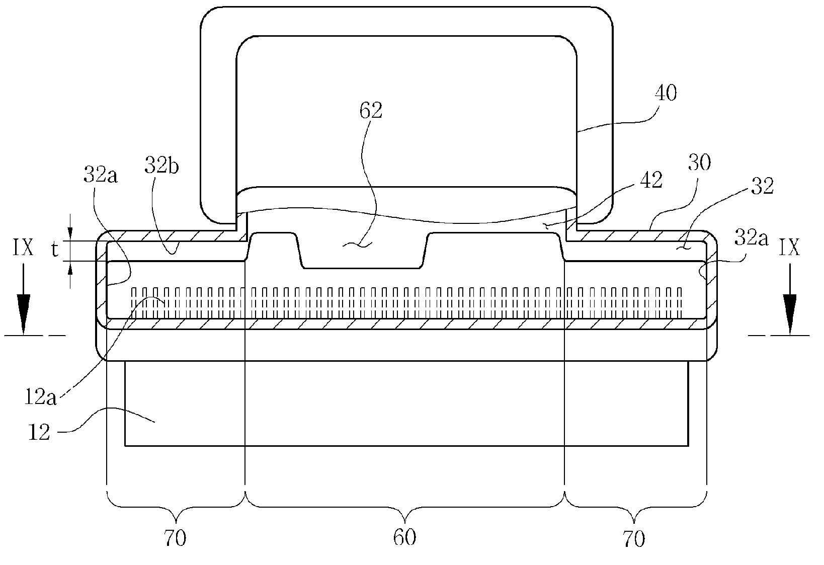
[0026]FIG. 2 is a front elevational view illustrating a cooling system for hybrid vehicles in accordance with the present invention and FIG. 3 is a sectional view illustrating, in more detail, the present cooling system for hybrid vehicles.

[0027]A brief description of a hybrid vehicle will precede the description of the cooling system for hybrid vehicles in accordance with the present invention.

[0028]As illustrated in FIGS. 2 and 3, the hybrid vehicle is provided with a battery case 3 having a battery storage room 3a formed therein. A battery 8 is received within the battery storage room 3a and is connected to an electric motor (not shown) to supply an electric...


PUM

PropertyMeasurementUnit
voltageaaaaaaaaaa
heightaaaaaaaaaa
electric voltageaaaaaaaaaa

Abstract

A cooling system for hybrid vehicles is provided with a battery case with a battery storage room for receiving a battery, a motor control unit for controlling an electric motor and a DC-DC converter for converting a voltage of the battery. The cooling system includes a blower for drawing an air existing in a passenger compartment of a vehicle, an introduction duct through which the air is introduced into the battery storage room to cool the battery, a first supply duct through which the air is supplied from the battery storage room to the DC-DC converter to cool the latter, a second supply duct through which the air is supplied from the battery storage room to the motor control unit to cool the latter, and an air distributor means for distributing the air flowing out of the battery storage room to the first supply duct and the second supply duct.

Description

[0001]This application claims the benefit of Korean Patent Application No. 10-2006-0010044, filed on Feb. 2, 2006, Korean Patent Application No. 10-2006-0070197, filed on Jul. 26, 2006 and Korean Patent Application No. 10-2007-0009289, filed on Jan. 30, 2007, the disclosure of which is hereby incorporated by reference as if fully set forth herein.FIELD OF THE INVENTION[0002]The present invention pertains to a cooling system for hybrid vehicles and, more particularly, to a cooling system for hybrid vehicles capable of simultaneously cooling a battery, a motor control unit and a DC-DC converter all together by use of an air introduced.BACKGROUND OF THE INVENTION[0003]A hybrid vehicle, which refers to a motor vehicle equipped with an electric motor and an internal combustion engine in combination, is known to enjoy increased fuel economy and reduced upkeep costs and is an environmentally friendly vehicle that produces an extremely low level of exhaust emission, thus helping to reduce a...

Claims


Application Information

Patent Timeline
Patent Type & Authority Patents(United States)
IPC IPC(8): H01M10/50B60H1/00B60K11/00
CPCH01M10/5004H01M10/5016H01M10/5022H01M10/5067H01M10/5097H01M10/5073Y10S903/952Y10S903/903Y10S903/907H01M10/613H01M10/625H01M10/633H01M10/6563H01M10/6566H01M10/667Y02E60/10
Inventor PARK, MIN WOOLEE, DAE WOONGKIM, HYUNG JOOSON, IL GUKLEE, SUNG JE
Owner HANON SYST
Learn More