
Determination of thermal resistance using infrared thermography

a technology of thermal resistance and infrared thermography, which is applied in the field of infrared camera, can solve the problems of hidden from view, difficult to determine the actual r-value of insulation without at least partially damaging the wall, and difficult to ascertain the effective r-value of the wall, etc., and achieve the effect of cost saving

Active Publication Date: 2012-05-29
TELEDYNE FLIR LLC
View PDF10 Cites 36 Cited by
  • Summary
  • Abstract
  • Description
  • Claims
  • Application Information

AI Technical Summary

Benefits of technology

"The patent describes a method, system, and machine-readable medium for determining the thermal resistance of building materials using infrared cameras. The system captures infrared images of a wall and a target in a first environment on one side of the wall, measures the temperature of a second environment on the other side of the wall, and calculates the thermal resistance value of the wall based on the wall surface temperature, the target surface temperature, and the temperature of the second environment. The technical effect of this invention is to provide a non-destructive and cost-effective method for evaluating the thermal performance of building materials."

Problems solved by technology

Unfortunately, after insulation or other building materials are installed in a wall of a structure, it is often difficult to ascertain the effective R-Value exhibited by the wall.
For example, after insulation is installed, it is typically hidden from view.
As a result, it may be difficult to determine the actual R-Value of the insulation without at least partially damaging the wall.
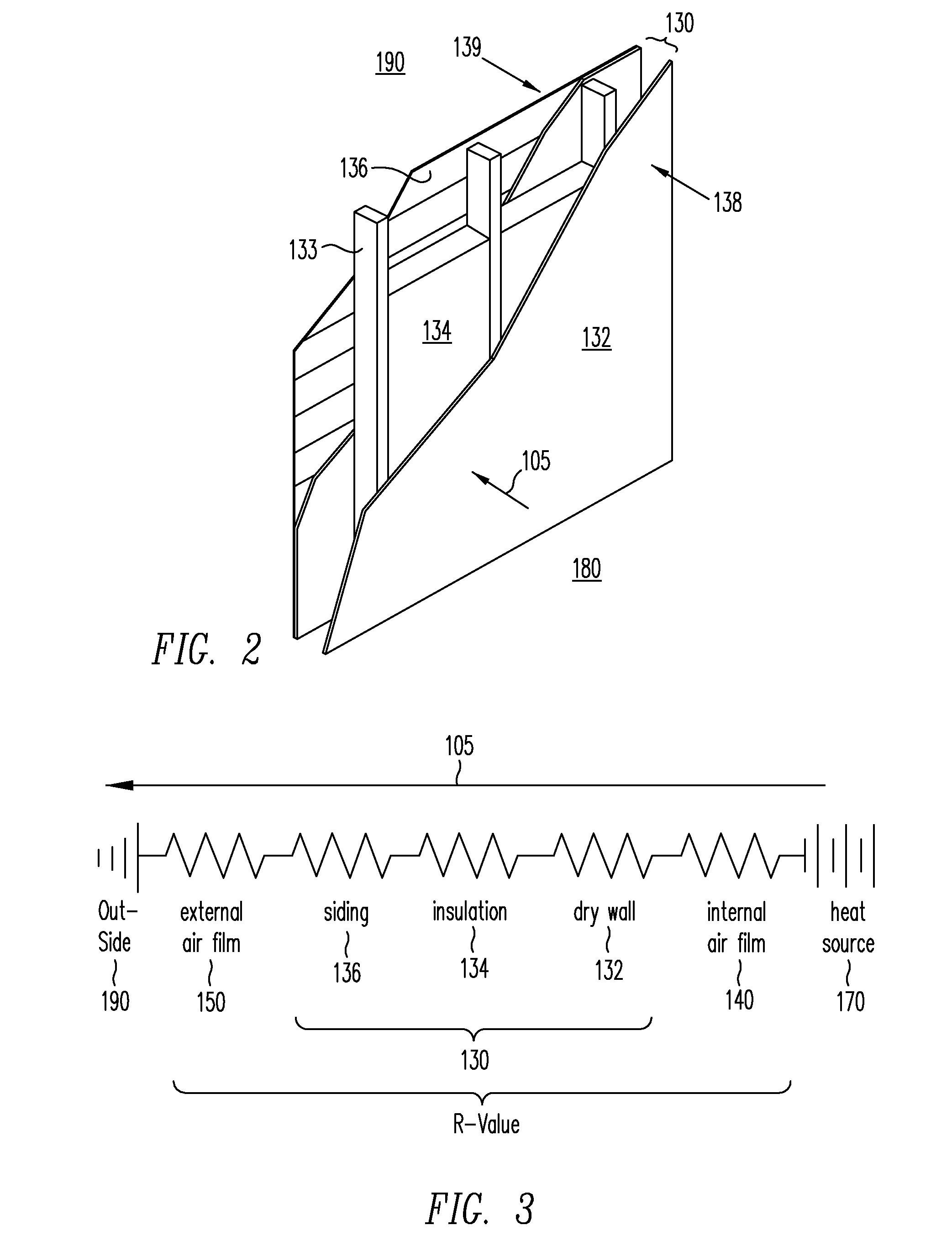
Moreover, because the wall's overall resistance to heat flow may depend on other wall components (e.g., drywall, siding, and / or other materials), knowing the R-Value of insulation in the wall will not necessarily provide an accurate indication of the overall R-Value exhibited by the wall.

Method used


Image

  • Determination of thermal resistance using infrared thermography
  • Determination of thermal resistance using infrared thermography
  • Determination of thermal resistance using infrared thermography

Examples


Embodiment Construction

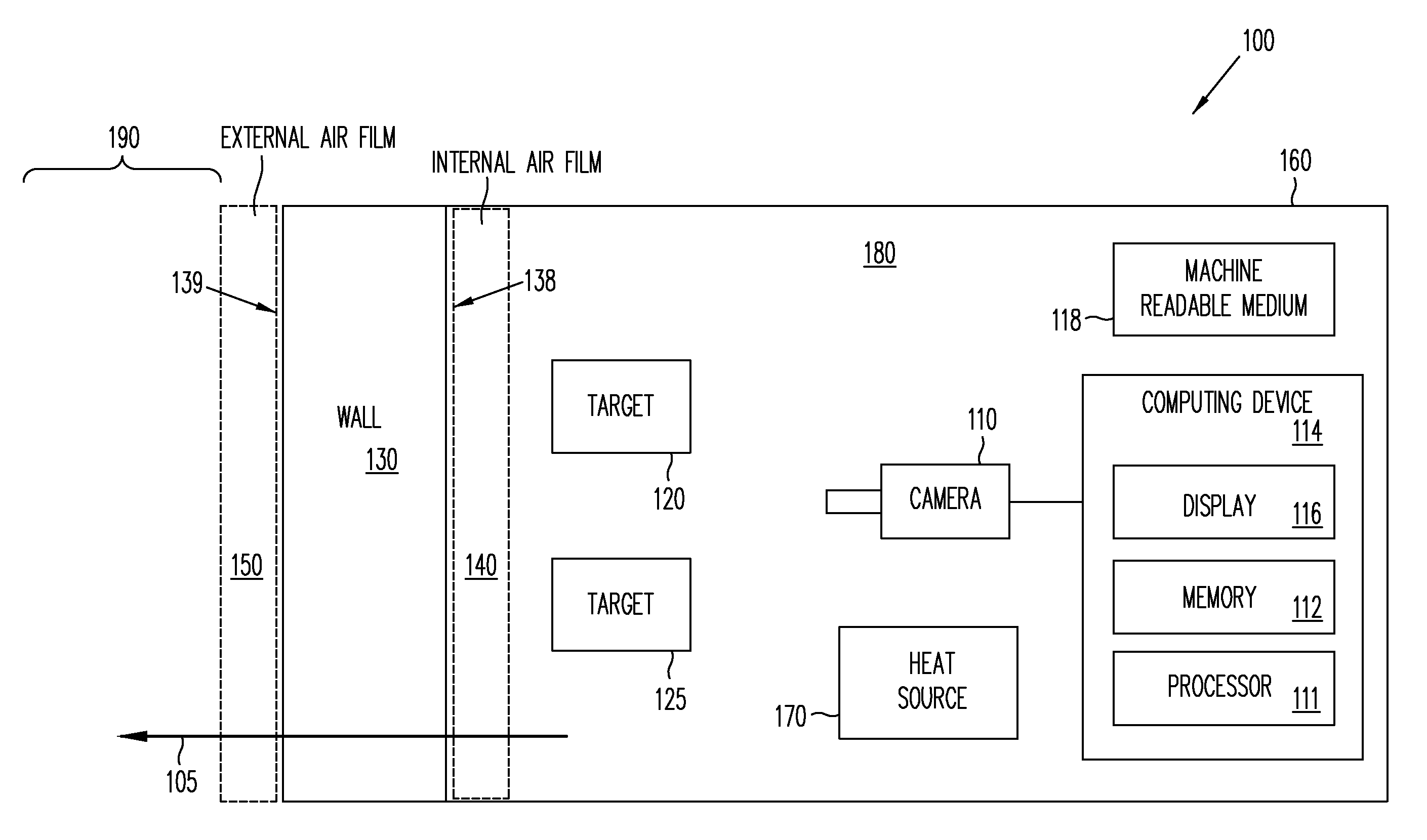
[0021]Various techniques are provided for determining thermal resistance values of building materials through the use of infrared cameras. For example, in one embodiment, an infrared camera may be used to capture one or more infrared images of a wall. Using temperatures obtained from the images, a thermal resistance value associated with the wall may be determined. Potential cost savings associated with adjusting the thermal resistance value may also be determined. Although thermal resistance values will be described herein with regard to R-Values in English units, it will be appreciated that the various techniques described herein may be similarly used to determine other thermal resistance values such as R-Values expressed in metric units, U-Values, and / or other values where appropriate. When referring to temperature differences, it will also be appreciated that degrees Rankine and Kelvin may be substituted for degrees Fahrenheit and Celsius where appropriate.

[0022]Referring now to...


PUM

PropertyMeasurementUnit
period of timeaaaaaaaaaa
time periodaaaaaaaaaa
emissivityaaaaaaaaaa

Abstract

Various techniques are provided for determining thermal resistance values of building materials through the use of infrared cameras. In one example, an infrared camera may be used to capture one or more infrared images of a wall. Using temperatures obtained from the images, a thermal resistance value such as an R-Value associated with the wall may be determined. Potential cost savings associated with adjusting the thermal resistance value may also be determined.

Description

BACKGROUND[0001]1. Field of the Invention[0002]The present invention generally relates to infrared measurement techniques, and more particularly to the use of infrared cameras to determine attributes of building materials.[0003]2. Related Art[0004]As is well known, R-Values can be used to identify the resistance to heat flow exhibited by building materials. For example, insulation or other building materials may be rated by R-Values (for example, R-13, R-19, or other values), wherein higher R-Values indicate better insulation performance. In the United States, R-Values are generally expressed in English units: F*ft2*Hour / BTU. By dividing English R-Values by 5.673, the R-Values can be expressed in metric units: C*m2 / W. In various applications, insulation performance may be identified by the reciprocal of R-Value, called U-Value: U=1 / R.[0005]Unfortunately, after insulation or other building materials are installed in a wall of a structure, it is often difficult to ascertain the effect...

Claims


Application Information

Patent Timeline
Patent Type & Authority Patents(United States)
IPC IPC(8): G01N25/20G01J5/00G01N25/18
CPCG01N25/18G01N25/72
Inventor MADDING, ROBERT P.
Owner TELEDYNE FLIR LLC
Learn More