
Device for cutting out and opening/closing an orifice in a wall at the bottom of the sea

Active Publication Date: 2012-05-29
SAIPEM SA
View PDF10 Cites 9 Cited by
  • Summary
  • Abstract
  • Description
  • Claims
  • Application Information

AI Technical Summary

Benefits of technology

[0054]Another advantage of the present invention is that a device of the invention can be relatively compact, so that it is possible to install a plurality of devices of the invention side by side on a single wall of a leaking tank, as explained below.
[0055]If the wall on which it is desired to anchor the base is the wall of a tank that presents a hole through which a polluting fluid contained in the tank is escaping at the sea bottom, said base may be used for fitting any extractor device thereto. More particularly, said base may itself serve to anchor any device and in particular a shuttle reservoir for collecting fluid from a tank having said base anchored on a wall thereof.
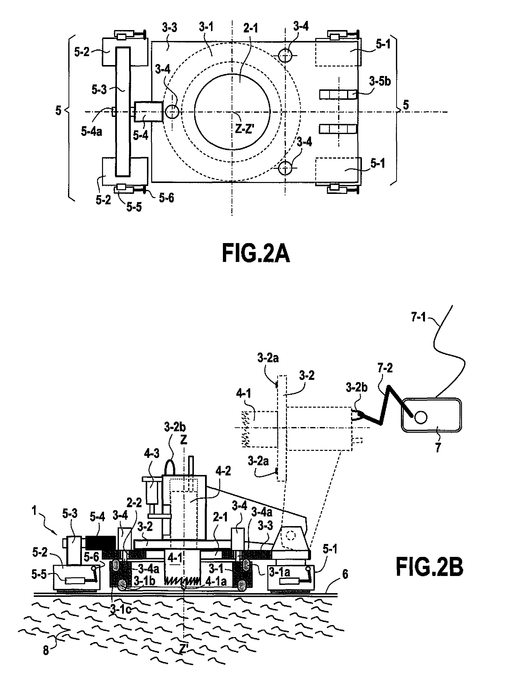
[0056]In a device for recovering a fluid flowing through an opening in said wall, said base includes a large second orifice that is central and cylindrical in shape about an axis lying in said longitudinal direction ZZ′, with a diameter of at least 200 mm, and more particularly a diameter lying in the range 300 mm to 800 mm, and it enables a corresponding small first orifice to be made in the wall having a diameter of 100 mm to 500 mm, and in particular lying in the range 200 mm to 300 mm, for removing a fluid from a tank having said base anchored on a wall thereof.
[0057]The present invention is more particularly advantageous for making said first circular orifices with a diameter lying in the range 100 mm to 300 mm.
[0059]said base including a platform including a said large second orifice; and
[0061]a cylindrical wall defining a said cylindrical chamber disposed axially relative to said large second orifice on the underside of said platform, said cylindrical wall including a top elastomer gasket on its top edge suitable for establishing sealing between said platform and said cylindrical wall, and a bottom elastomer gasket on its bottom edge suitable for establishing sealing between said cylindrical wall and said bottom wall; and

Problems solved by technology

When a cargo vessel or an oil tanker is shipwrecked, the ship generally sinks after being badly damaged and after losing some of its cargo.
When the depth of water is considerable, i.e. 100 meters (m) or 200 m, recovering the wreck or refloating it is generally not envisaged, however the hull must be completely emptied and cleaned so that long-term corrosion of the structure leading to localized or generalized holes will not also lead to the content of the ship being released, thereby creating pollution that may endure over years or even tens of years.
But in practice, the wreck is generally broken, and only exceptionally will it be in a horizontal position on the sea bottom.
However, at greater depth, such interventions become very complex and they are preferably performed by robotic systems, thereby making the task very difficult.
However, in those systems, the module anchored on the wall is designed to exhaust the cargo from the wreck to the surface by means of a pipe and pumping, such that the amount of traction exerted on the module or base is relatively small.
In contrast, when the cargo is extremely viscous and the wreck is situated in very great depths, e.g. more than 1000 m or even more than 3000 m or 4000 m, the method that consists in installing a pipe between the sea bottom and the surface becomes practically impossible because of the very great head loss that occurs along the pipe.
Even with extremely powerful pumping at the wreck, flow rates remain low and the risk of creating plugs and blockages in the pipe are high.
Furthermore, for such extremely viscous cargoes, it is desired to avoid using pumps, since they are very difficult to operate at very great depth because of the power they require, and it is then preferred to increase the diameter of the orifice made through the hull so that the crude oil can rise naturally simply because of the difference in density between said crude oil and sea water.
The complex structure of the device of EP 1 568 600 with an upper structure supporting anchor means and second cutter means for cutting the wall that are different from the first cutter means used for anchoring the base make that device complicated to implement since it requires the upper structure to be separated from the base and to be raised to the surface after the base has been anchored and the bottom wall pierced.

Method used


Image

  • Device for cutting out and opening/closing an orifice in a wall at the bottom of the sea
  • Device for cutting out and opening/closing an orifice in a wall at the bottom of the sea
  • Device for cutting out and opening/closing an orifice in a wall at the bottom of the sea

Examples


Embodiment Construction

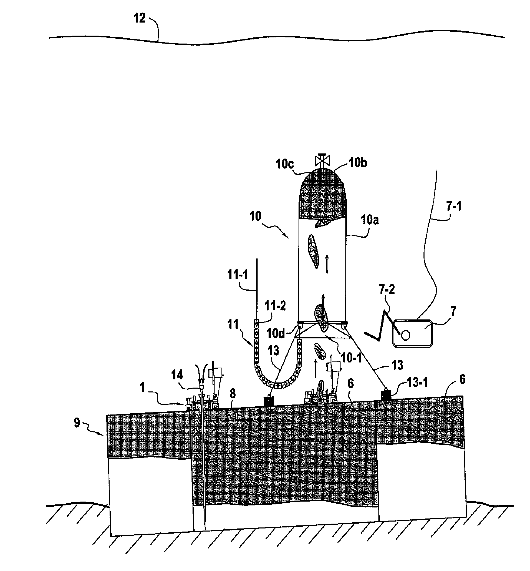
[0125]FIG. 1 is a side view in section of the wreck of a ship containing polluting substances, such as heavy fuel 8, stored in the tanks 9 of said ship, and two devices 1 of the invention that have enabled the hull 2 to be drilled at two locations. Each of these devices includes a tilting cover shown in the open position, but also suitable for closing the orifice. The shuttle reservoir 10 having a capacity of 150 m3 is positioned vertically above a first said device 1 of the invention and it receives the polluting substance 8 that escapes from said tank and that moves vertically upwards at slow speed, given its density which remains less than the density of sea water. Said shuttle 10 is held laterally by cables connected to deadweight blocks 13-1 weighing 250 kilograms (kg), merely placed on the wall 6 of the ship, the vertical forces due to the buoyancy of the reservoir 10 are counterbalanced by a handling and stabilizing device 11 with heavy blocks 11-2 described below with refere...


PUM

PropertyMeasurementUnit
Timeaaaaaaaaaa
Forceaaaaaaaaaa
Pressureaaaaaaaaaa

Abstract

The present invention relates to a method of cutting (1) a small first orifice (1-1) in a wall (6) at the bottom of the sea and of opening / closing said first orifice, the method comprising anchoring a base (2) that includes a large second orifice (2-1) and a cutter device comprising: a said base, a deformable stopper (3) connected to said base and enabling said large second orifice to be opened or closed depending on the position of the stopper on the base, circular cutter means (4) secured to said base, and anchor means (5) secured to said base and suitable for anchoring said base reversibly on said wall (6). The present invention also provides a method of recovering a viscous fluid that is lighter than water, such as a polluting effluent, and that is contained in a tank of a sunken and / or damaged vessel resting on the sea bottom.

Description

PRIORITY CLAIM[0001]This is a U.S. national stage of application No. PCT / FR2008 / 050356, filed on Mar. 3, 2008. Priority is claimed on the following application(s): Country: France, Application No.: 0701540, Filed: Mar. 2, 2007, the content of which is incorporated here by reference.FIELD Of THE INVENTION[0002]The present invention relates to a device for cutting out a small orifice in a wall at the bottom of the sea and for opening / closing said small orifice.[0003]More particularly, the wall may form part of a wrecked ship or a tank of a wrecked ship on which it is required to take action.[0004]The present invention also provides a method of installing and anchoring a base on a wall at the bottom of the sea and then cutting said wall open, in particular to allow a fluid to pass through the orifice as created in this way in said wall, and be recovered. The method is particularly useful when it is desired to implement a method and an installation for recovering effluents at sea and mo...

Claims


Application Information

Patent Timeline
IPC IPC(8): B63B9/00B63G7/04B23G1/00B23B47/00B23B49/00
CPCB63C7/006E21B7/124E21B43/0122Y10T408/554E21B41/08Y10T137/0318
Inventor BAYLOT, MICHELGALLETTI, ROBIN
Owner SAIPEM SA
Learn More