
Air-conditioning control algorithm employing air and fluid inputs

a technology of air-conditioning control and fluid input, which is applied in the direction of computer control, refrigeration components, ratio control, etc., can solve the problems of increasing equipment wear, periodic temperature fluctuations, and not being able to provide for optimizing the temperature fluctuations of coolant fluid

Active Publication Date: 2012-05-22
CARRIER CORP
View PDF26 Cites 13 Cited by
  • Summary
  • Abstract
  • Description
  • Claims
  • Application Information

AI Technical Summary

Benefits of technology

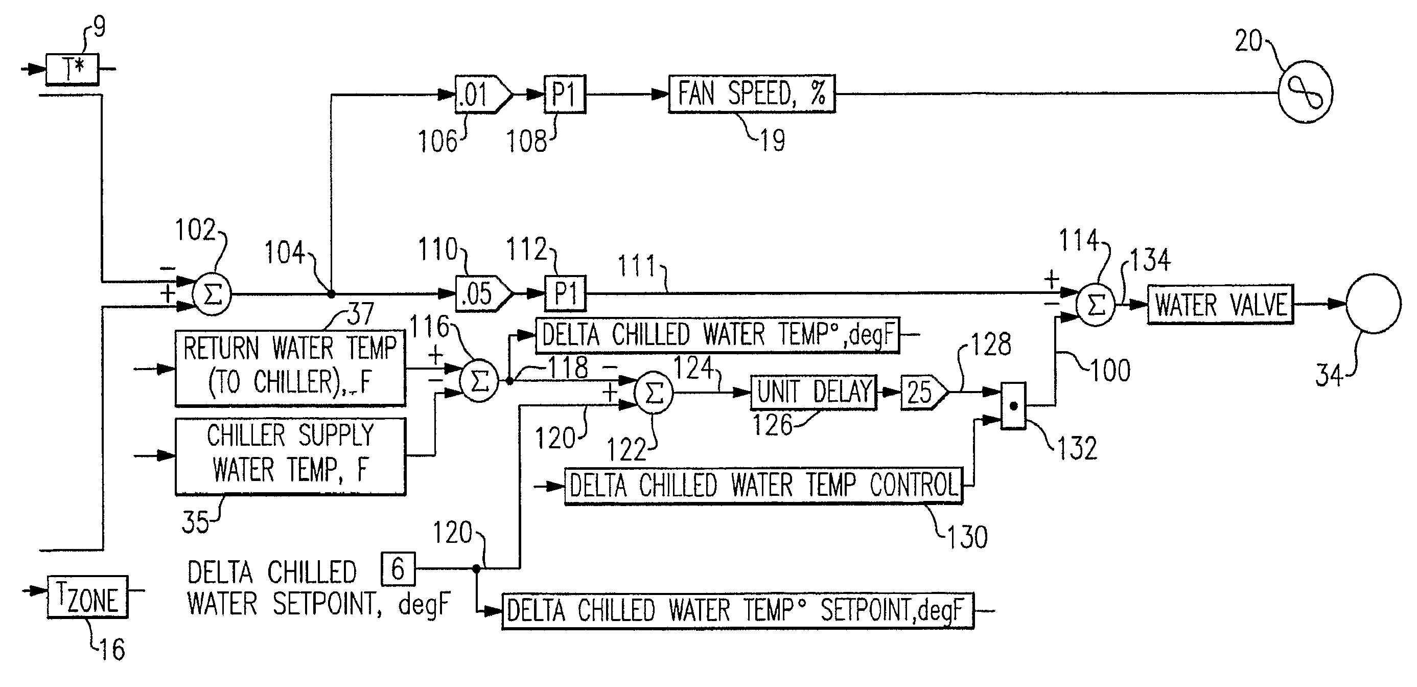
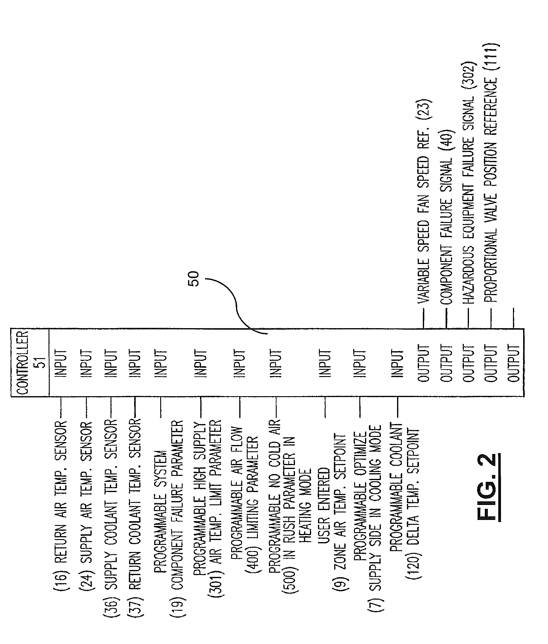
The patent describes a control algorithm for an air-conditioning system that uses multiple sensors to control the system's actuators. The algorithm can adjust the temperature between the inlet and outlet of the coolant fluid in the system to optimize the temperature adjusting coil while maintaining the desired zone temperature. It can also detect system component failure and provide a safety warning. Additionally, it can create desirable effects in the controlled zone by using the supply air and return air temperatures.

Problems solved by technology

This cycling is undesirable because it causes the controller to frequently adjust the system components in an effort to achieve the setpoint in the zone, and as a result, it merely increases equipment wear and causes periodic temperature fluctuations above and below the setpoint in the zone.
Certain algorithms exist to minimize the aforementioned cycling using only the ambient temperature in the zone or the return air sensor, but without additional sensors, they are not capable of providing for optimization of the temperature fluctuations in the coolant fluid, detecting air-conditioning system mechanical component failures, providing supply end equipment overheating alerts to a system user or building management system, or providing smart temperature controls for an air conditioned zone.

Method used


Image

  • Air-conditioning control algorithm employing air and fluid inputs
  • Air-conditioning control algorithm employing air and fluid inputs
  • Air-conditioning control algorithm employing air and fluid inputs

Examples


Embodiment Construction

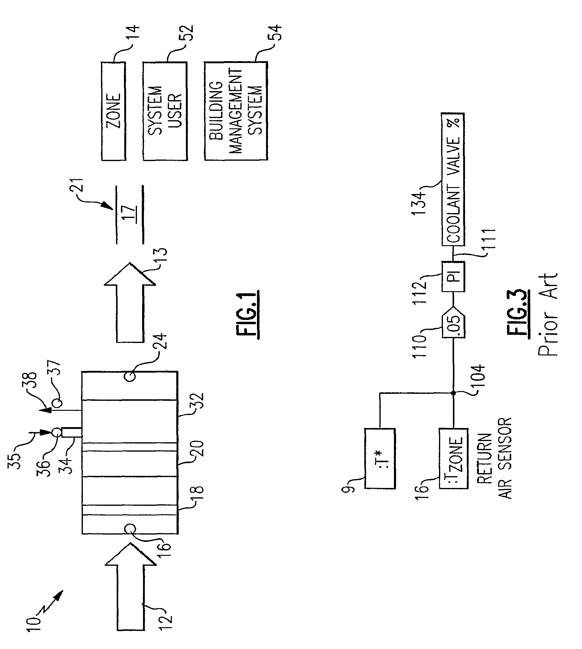
[0019]Referring initially to FIG. 1, there is illustrated a diagrammatical depiction of a zone air-conditioning system generally referenced at 10, that illustrates a direction of air flow coming into the system 12, from the air-conditioned zone 14 and a direction of conditioned air flow exiting the system 13. Entrance of the air flow from the zone 14, passes over a return air temperature sensor 16, then through a supply side filter 18, then through at least one supply side air fan 20, a supply side air temperature adjusting coil 32, and finally over a supply air temperature sensor 24. The conditioned air is then supplied to the zone 14. A supply side proportional coolant fluid flow valve 34, is disposed in the piping that the supplies the supply coolant fluid 35, to the supply side of the air temperature adjusting coil 32. The temperature of the supply coolant fluid 35, is sensed by a supply coolant fluid temperature sensor 36, if present, or broadcast by a building monitoring syste...


PUM

PropertyMeasurementUnit
temperatureaaaaaaaaaa
delta temperatureaaaaaaaaaa
temperatureaaaaaaaaaa

Abstract

Sensing, actuation of apparatus, and a control algorithm for use in automatically controlling an air-conditioning system by sensing multiple conditions and responding by actuating the mechanical components of the air-conditioning system to optimize the temperature of the coolant fluid, provide improved zone temperature control, provide status of system components, and provide an alert if there is overheating of a supply side system mechanical component.

Description

CROSS REFERENCE TO RELATED APPLICATIONS[0001]This application is related to patent application identified by both of which are subject to assignment to Carrier Corporation, and each of which is being filed on even date herewith.FIELD OF THE INVENTION[0002]The present invention relates to the field of temperature control systems, and in particular, to a control algorithm for use in automatically controlling an air-conditioning system by sensing multiple conditions and responding by actuating the mechanical components of the air-conditioning system.BACKGROUND OF THE INVENTION[0003]Many air conditioning zone control systems include a single sensor that monitors the temperature of the ambient air or the temperature of the air returning from the zone whose temperature is being controlled. This sensor provides feedback to an air-conditioning system controller in order for the controller to adjust various air-conditioning components such as supply air fans, coil coolant fluid proportional ...

Claims


Application Information

Patent Timeline
Patent Type & Authority Patents(United States)
IPC IPC(8): G05B21/00G05D23/00G05D23/32G01M1/38G05B13/00F24D19/10F24F11/053G05B15/00F25D17/04G01K13/00F25B29/00F25B49/00F24F11/76
CPCF24F11/0009F24F11/0012F24F11/008F24F11/0079Y02B30/746F24F11/30F24F2110/10F24F11/77F24F11/83Y02B30/70F24F11/52F24F11/63F24F11/84F24F11/38F24F2140/00
Inventor JOSSERAND, OLIVIERROYET, ERICRENAULT, PATRICKKOLK, RICHARD
Owner CARRIER CORP
Learn More