
Muscle training device with muscular force measurement function for controlling the axial torque of a joint axle

a training device and axial torque technology, applied in the direction of force/torque/work measurement apparatus, gymnastic exercise, instruments, etc., can solve the problems of difficult to accurately determine the limit of the muscular force of the trainee, difficult to achieve effective training, and the load applied to the limb of the trainee cannot be correctly controlled. , to achieve the effect of safe measurement and training of the muscular force, and performing the desired muscular force training safely and effectively

Active Publication Date: 2012-05-22
OKI ELECTRIC IND CO LTD
View PDF12 Cites 29 Cited by
  • Summary
  • Abstract
  • Description
  • Claims
  • Application Information

AI Technical Summary

Benefits of technology

The present invention provides a training device with muscular force measurement function, which ensures safe measurement and training of muscular force without applying an excessive load on the trainee. The training device includes a robot arm adjustable according to the length of either the upper or lower limb of the trainee, a mounting fixture for mounting the robot arm, an angular sensor for measuring the angle of rotation of the joint axle, a torque sensor for measuring the axial torque, and a controller for controlling the torque. The controller stores the relationship between the measured axial torque and the angle of the joint axle, and calculates the reactive force generated in the assumed virtual model and applies a training load substantially equivalent to the reactive force to the trainee. The training device with muscular force measurement function ensures a safe measurement and training of muscular force.

Problems solved by technology

It is, however, difficult to correctly determine the limit of the muscular force of the trainee.
However, since the muscular force training device of pseudo-bicycle type maintains for a comparatively short period of time a situation where a load is applied to the target muscle, compared with that in the entire exercise, it is difficult to achieve effective training.
Consequently, a load applied to the limb of the trainee cannot correctly be controlled unless the influence of the own weight of the movable parts of the device and the weight of his or her limb is taken into account.

Method used


Image

  • Muscle training device with muscular force measurement function for controlling the axial torque of a joint axle
  • Muscle training device with muscular force measurement function for controlling the axial torque of a joint axle
  • Muscle training device with muscular force measurement function for controlling the axial torque of a joint axle

Examples


Embodiment Construction

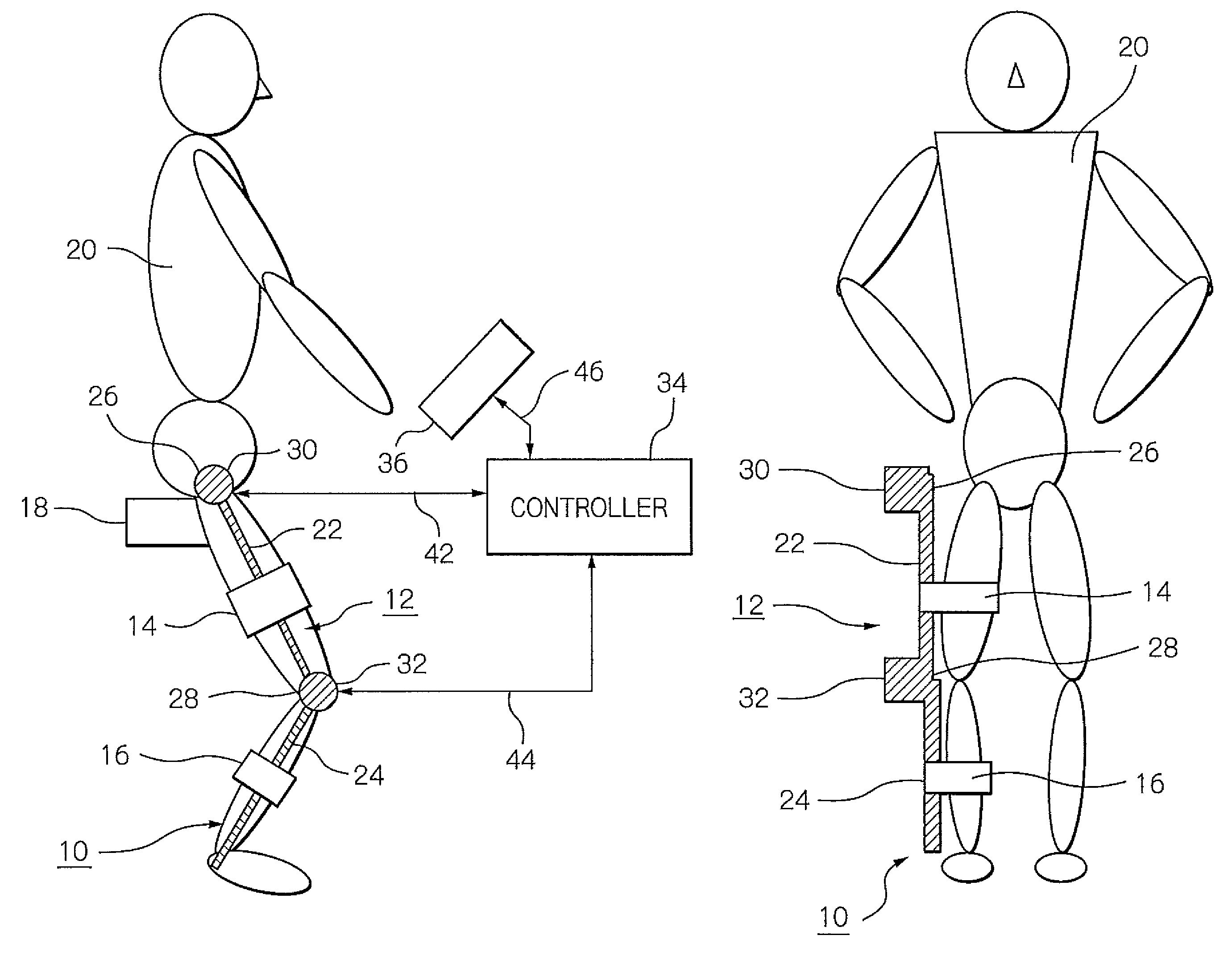
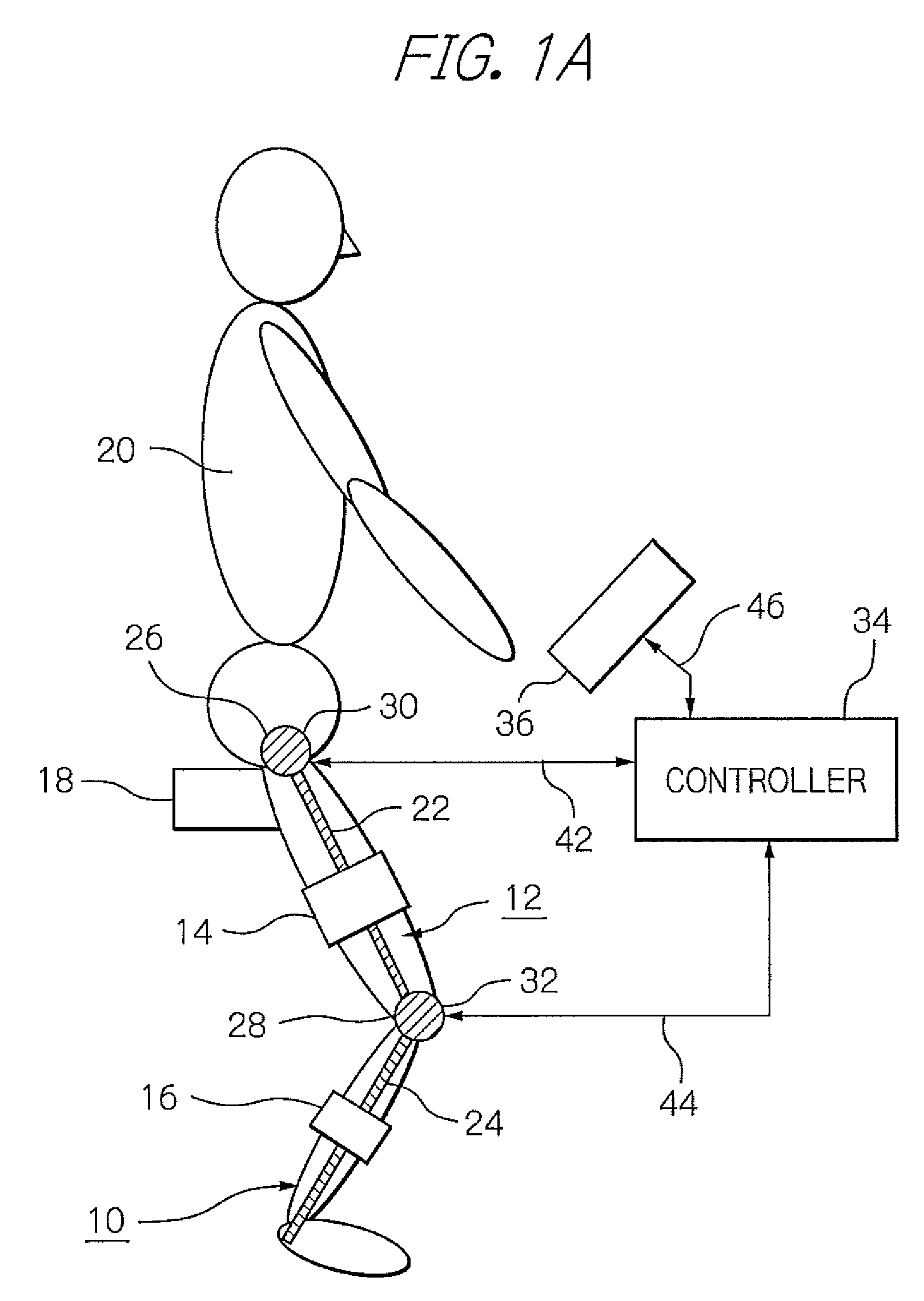
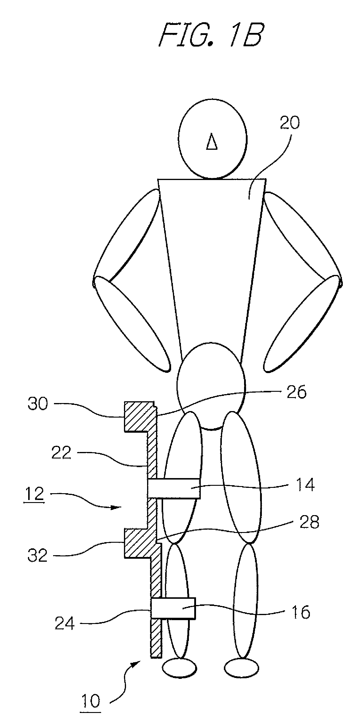
[0044]In the following, with reference to the accompanying drawings, preferred embodiments of a training device with muscular force measurement function in accordance with the invention will be described in more details. Referring first to FIG. 1A, the embodiment of a training device with muscular force measurement function will be described in connection with the constitution and movement of the training device 10.

[0045]The training device 10 is so arranged that a robot arm 12 is mounted on a trainee 20 with mounting fixtures 14 and 16 to measure a change in angle of the joint axles 30 and 32 of a limb of the trainee 20 with an angular sensor 54 or 56, FIG. 3, and based on the measured angular change a controller 34 calculates an angular rate of the joint axles 30 and 32 in a direction in which a load has been applied to then store as the maximum muscular force a load at the time when the angular rate has exceeded a predetermined value and stops applying the load. Thereby, the time...


PUM


Abstract

A training device measures, after its robot arm is mounted on a trainee, a change in angle of the joint axles of a limb of the trainee with angular sensors. Based on the angular change measured, a controller calculates an angular rate in the direction in which a load is applied, stores as the maximum muscular force a load at the time when the angular rate has exceeded a predetermined value, and stops applying the loads.

Description

BACKGROUND OF THE INVENTION[0001]1. Field of the Invention[0002]The present invention relates to a muscle training device with muscular force measurement function.[0003]2. Description of the Background Art[0004]Conventionally, systems or devices have been proposed which exploit a bi-articular link mechanism, such as a bi-articular arm device, and for measuring and training muscular force. Such proposals are disclosed in Japanese patent laid-open publication Nos. 2000-210272 and 2007-61137 as well as in U.S. patent application publication No. US 2008 / 0026923 A1 to Kadota. In such systems and devices, outputs of the muscles in the antagonistic mono- and bi-articular muscle groups of a trainee are measured with a pressure sensor. Then, a limb of a trainee is caused to exert force in a plurality of predetermined directions with his or her isometrical maximum effort, on the basis of which a hexagonally shaped output distribution chart is formed to evaluate function-based muscles of praxi...

Claims


Application Information

Patent Timeline
Patent Type & Authority Patents(United States)
IPC IPC(8): A61B5/22A63B21/00
CPCA61B5/1071A61B5/224A61B5/6828A61B5/4528A61B5/6824
Inventor KADOTA, KENJITOKITA, MAMORUNISHINO, NOBUHARU
Owner OKI ELECTRIC IND CO LTD
Learn More