
Microphone having a three-pin socket and a USB socket

a three-pin socket and microphone technology, applied in the field of microphones, can solve the problems of many occasions when the microphone cannot be used normally, and achieve the effect of saving a very large space, reducing the dimension of the finished product, and reducing the size of the microphone casing

Inactive Publication Date: 2012-05-15
WU YING JUI
View PDF4 Cites 10 Cited by
  • Summary
  • Abstract
  • Description
  • Claims
  • Application Information

AI Technical Summary

Benefits of technology

Enables the microphone to be used on various occasions by allowing connection with both three-hole signal lines and USB data lines, reducing the device's size and enhancing compatibility while providing an adapter for different USB plug dimensions.

Problems solved by technology

Those differences shall make the microphone fail to use normally at many occasions, for examples, the microphone only having a three-pin socket cannot match a USB data line, in the same way, the microphone only having a USB socket cannot match a three-hole signal line.

Method used


Image

  • Microphone having a three-pin socket and a USB socket
  • Microphone having a three-pin socket and a USB socket
  • Microphone having a three-pin socket and a USB socket

Examples


first embodiment

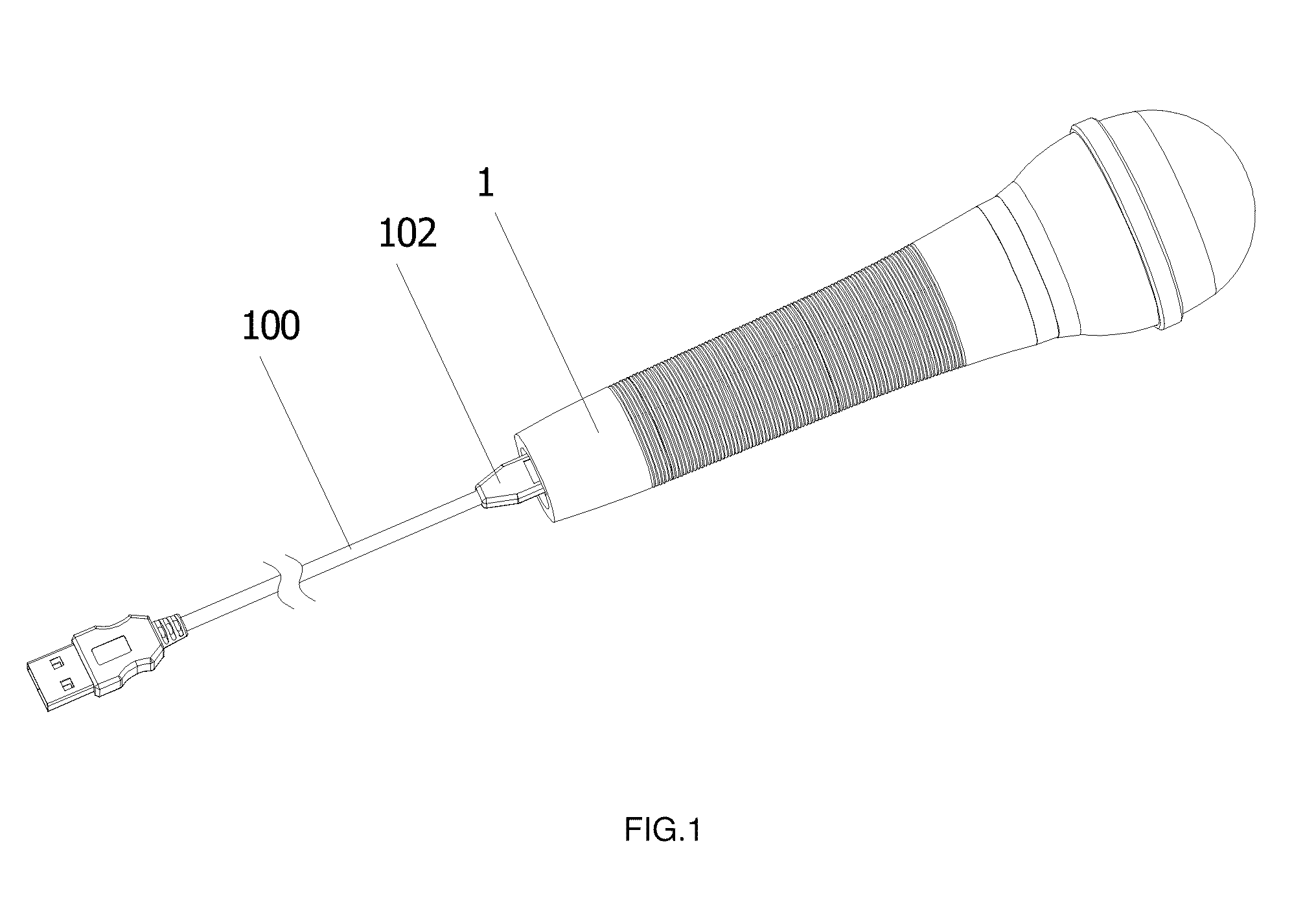
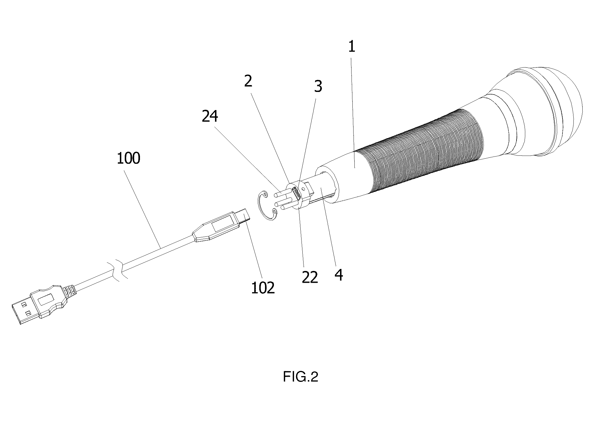
[0017]As shown in FIG. 1 to FIG. 3, the microphone in accordance with the present invention comprises a microphone casing 1, a three-pin socket 2, a first USB socket 3 and a PCB board 4.

[0018]The microphone casing 1 is a hollowly cylindraceous.

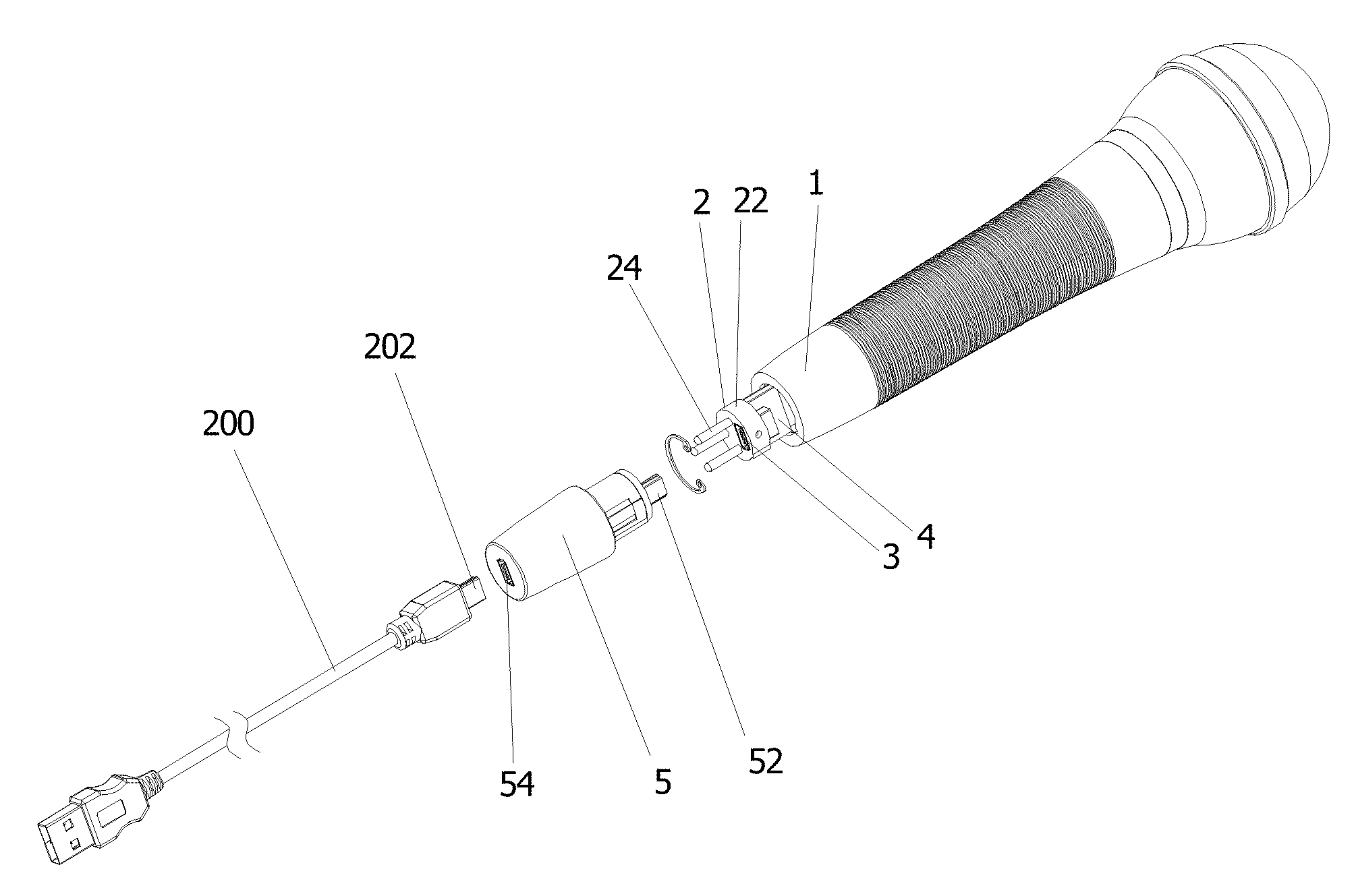
[0019]The three-pin socket 2 is fixed at the back end of the inner chamber of the microphone casing 1. The three-pin socket 2 comprises an inserted block 22 and three pins 24. The inserted block 22 is fixed at the back end of the inner chamber of the microphone casing 1. The three pins 24 are fixed on the inserted block 22 and surround to form a triangular position.

[0020]The first USB socket 3 is fixed within the three-pin socket 2. The first USB socket 3 is embedded in the inserted block 22 of the three-pin socket 2.

[0021]The PCB board 4 is fixed between the three pins 24 of the three-pin socket 2 and the first USB socket 3. The three-pin socket 2 and the first USB socket 3 are respectively fixed on the two opposite surfaces of the PCB board ...

second embodiment

[0029]In the second embodiment, the microphone comprises a three-pin socket 2 and a USB socket 3 in order to match not only a three-hole signal line but also a USB data line 100, so the microphone can be normally used at all occasions. The first USB socket 3 is fixed within the three-pin socket 2, so the dimension of the microphone casing 1 is reduced, so that the dimension of the finished product is reduced so as to save a very large space. Furthermore, the microphone comprises a USB adapter 5, when the USB plug 202 of the USB data line 200 has a different dimension from the first USB socket 3, the adapter 5 can aid the microphone to connect electrically with the USB plug 202.

[0030]In said two embodiments, the microphone casing 1 is traditionally cylindraceous. We shall realize that the shape of the microphone casing 1 can be easily changed to a different shape in another embodiment. The embodiments with different shapes of the microphone casing 1 also can carry out said technical ...


PUM


Abstract

A microphone comprises a three-pin socket, a first USB socket and a USB adapter. The first USB socket is fixed within the three-pin socket. The three-pin socket comprises an inserted block and three pins. The three pins are fixed on the inserted block. The first USB socket is embedded in the inserted block. The USB adapter comprises a USB plug which matches the first USB socket and a second USB socket which has a different dimension from the first USB socket. The USB plug and the second USB socket are connected electrically. The microphone can be normally used at all occasions. The dimension of the finished product is reduced so as to save a very large space. The microphone can be electrically connected with a USB data line with a USB plug having a different dimension from the first USB socket.

Description

BACKGROUND OF THE INVENTION[0001]The present invention relates to a kind of microphone, in particular to a microphone having a three-pin socket and a USB socket.[0002]With progress of technology and improvements of people's living conditions, various high-tech products are widely used more and more. For example, all kinds of microphones are used in a meeting room or other business occasions. We have designed a lot of different microphones to meet those requirements.[0003]In the current market, some microphones have a three-pin socket to connect a three-hole signal line, so that they are usually used in an ordinary acoustics or at a professional vocal concert etc. Other microphones have a USB socket to connect a USB data line, so that they are usually used in a computer or a digital product etc. There exist obvious differences between the standard of the three-pin socket and the standard of a USB data line, so is between the USB socket and the three-hole signal line. Those difference...

Claims


Application Information

Patent Timeline
Patent Type & Authority Patents(United States)
IPC IPC(8): H04R9/08
CPCH01R31/06H04R1/08H04R1/06
Inventor WU, YING JUI
Owner WU YING JUI
Learn More