
Rotating LED light on a magnetic base

a technology of led light and magnetic base, which is applied in the direction of applications, lighting support devices, and with built-in power, can solve the problems of affecting the light quality of the light, the light is usually difficult to adjust or rotate, and the hung light may swing or become unstable, etc., and achieves the effect of easy rotation

Active Publication Date: 2012-05-08
ULLMAN DEVICES
View PDF11 Cites 69 Cited by
  • Summary
  • Abstract
  • Description
  • Claims
  • Application Information

AI Technical Summary

Benefits of technology

"The present invention is about creating a rotating LED light on a magnetic base. The invention also includes an illumination system with an LED module and a mounting base. The LEDs mounted on the housing generate a light pattern, and the housing can be easily rotated to provide a rotatable mounting architecture. The battery system powers the LEDs. The technical effect of this invention is an easy-to-use, flexible LED light that can be easily moved and adjusted to provide illumination in different directions."

Problems solved by technology

The hung light may swing or become unstable.
If the light is fixed in place to avoid instability, the light is usually difficult to adjust or rotate.
Changing the illuminating direction and / or region of the light is difficult.
In addition, fixed lights restrict the applicable range of the light and transportation of the lighting source.
As such, they are fragile and have a relatively short operating life.
Furthermore, filament lamps are not the most economical to operate.
In addition, by producing light by heating a filament, incandescent lamps generate a great deal of heat.
This heat build up limits the effectiveness of traditional auxiliary lighting due to safety considerations and the possibility of unintentionally and adversely heating items in the near vicinity.
This heat generation also makes traditional puck lights less versatile in that some places in which such a light would be desired cannot accommodate a large buildup of heat (e.g. closets, shelves, etc.).
Moreover, traditional incandescent and fluorescent lights are quite inefficient.
Incandescent lights convert a large amount of energy to heat rather than light, and fluorescent lamps have a relatively high start up power consumption.

Method used


Image

  • Rotating LED light on a magnetic base
  • Rotating LED light on a magnetic base
  • Rotating LED light on a magnetic base

Examples


Embodiment Construction

[0040]This disclosure is drawn to a puck shaped LED light with a rotating magnetic base.

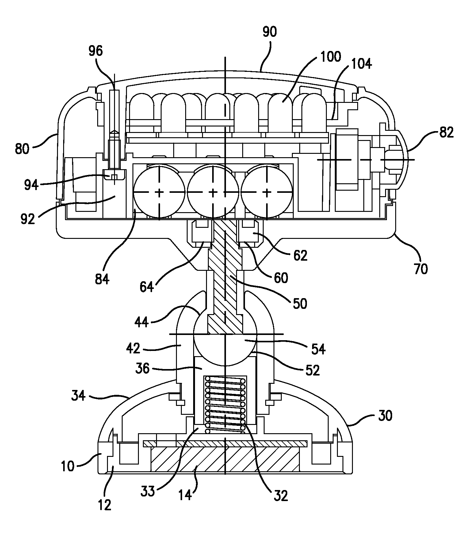
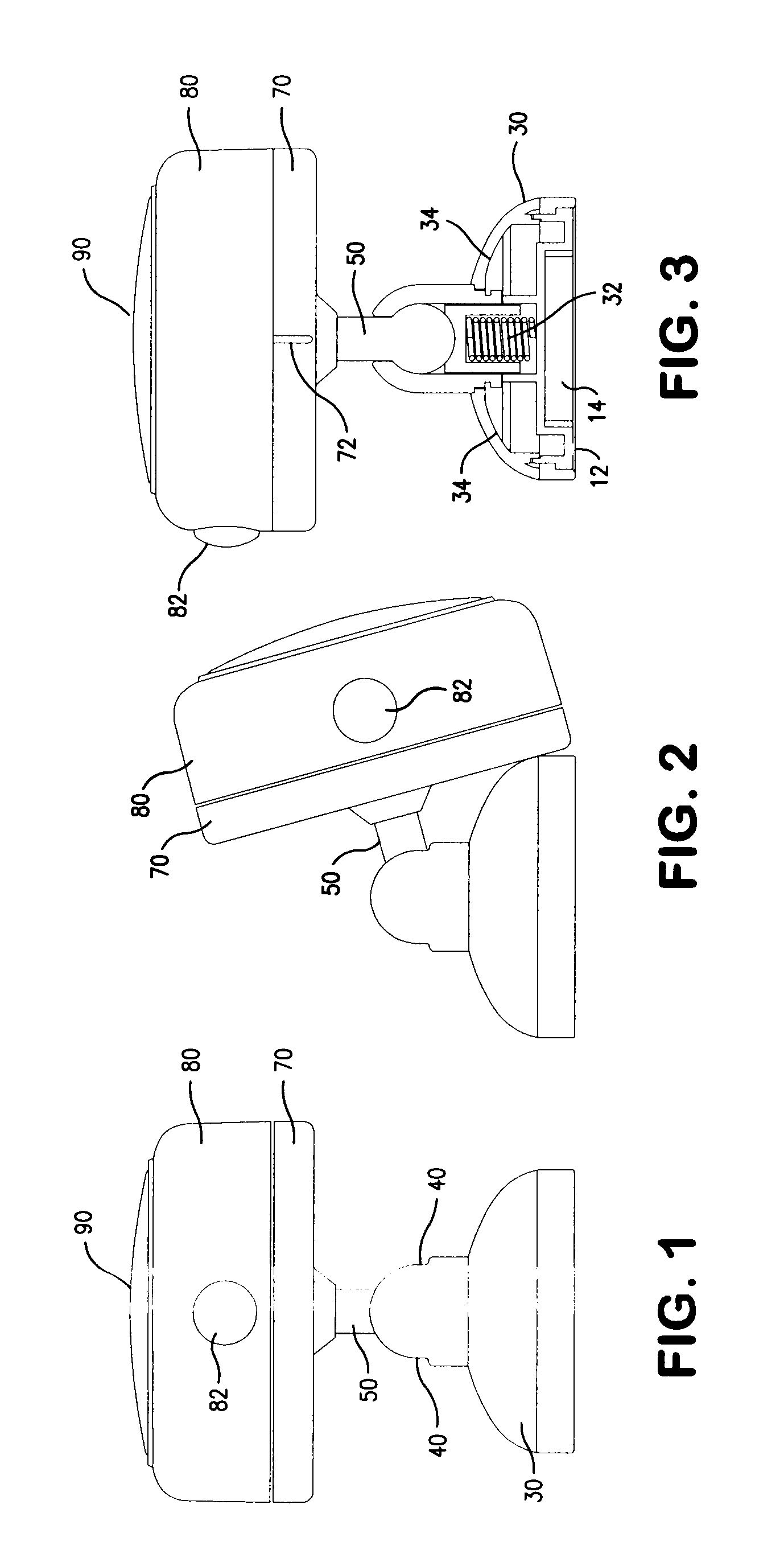
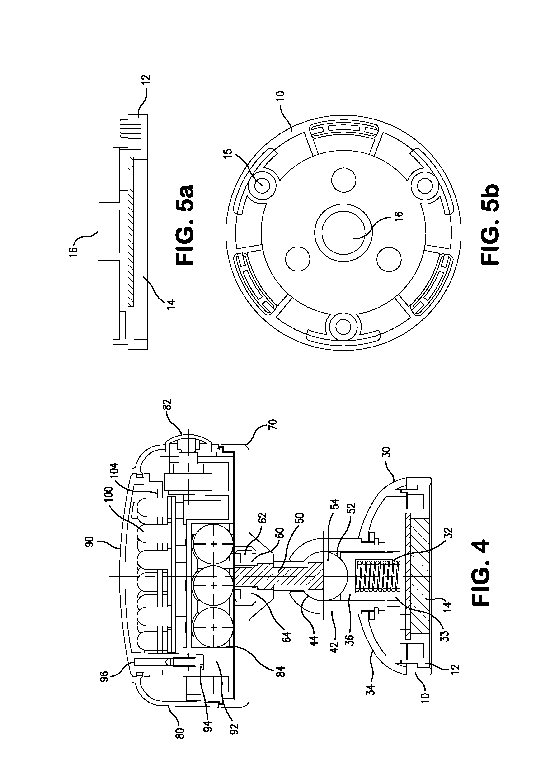
[0041]FIG. 1 details the puck shaped auxiliary light of the present disclosure. 10 depicts a magnetic base of the light attached to base 30 with notches 40 on both sides of the opening designed to fit post 50. The LED puck shaped housing 80 is threadedly attached to housing bottom 70, which is attached by any means well known within the art to post 50. Top 90 is the transparent window of the light.

[0042]The auxiliary light of the present invention may be made from any materials that are well known within the art. For instance, the base 30 may be composed of acrylonitrile butadiene styrene (ABS) plastic resin, the magnetic base 10 may be composed of a sturdy rubber or plastic material, the housings 80 and 70 may be composed of color anodized aluminum, ABS, mixtures thereof or the like and the post 50 may be composed of nylon resin, such as PA6+30% GF, steel alloy, such as carbon steel, mixtures th...


PUM


Abstract

A battery powered rotating LED lighting assembly with a magnetic base, a housing and a pivot post attached to the housing. The lighting assembly housing is supported by the pivot post, which is supported by a support assembly in the base.

Description

[0001]This invention relates to auxiliary lighting, and more particularly, to an auxiliary puck light with a pivoting head.[0002]Auxiliary lighting takes on many functionalities in the modern world. Lighting is needed in spaces that require visibility, such as closets, cabinets, under cabinets, tents, automobiles etc. In the working environment, a worker usually requires light in the region that he / she has to work. Either a separate person is employed to hold and direct the light or the light is hung in place. The hung light may swing or become unstable. If the light is fixed in place to avoid instability, the light is usually difficult to adjust or rotate. Changing the illuminating direction and / or region of the light is difficult. In addition, fixed lights restrict the applicable range of the light and transportation of the lighting source.[0003]The above lights generally utilize fluorescent or incandescent lamps as a light source. Fluorescent and incandescent lamps typically requ...

Claims


Application Information

Patent Timeline
Patent Type & Authority Patents(United States)
IPC IPC(8): F21S8/00
CPCF21S9/02F21V21/096F21V21/30F21W2131/301F21Y2115/10
Inventor COLEMAN, EDWARD S.JIANPING, QIU
Owner ULLMAN DEVICES
Learn More