Radio frequency directional coupler device and related methods

a technology of radio frequency and coupler, applied in the field of communication, can solve the problems of reducing the directivity of the device, affecting unable to meet the overall desired operating band, so as to improve the bandwidth and directivity, and reduce the number of components

Active Publication Date: 2012-05-01
HARRIS GLOBAL COMM INC
View PDF13 Cites 8 Cited by
  • Summary
  • Abstract
  • Description
  • Claims
  • Application Information

AI Technical Summary

Benefits of technology

[0008]In view of the foregoing background, it is therefore an object of the present invention to provide an improved bandwidth and directivity RF directional coupler with a reduced number of components.
[0010]A first monitoring circuit is carried by the first surface of the PCB and connected to the first monitoring port. The electronic device also includes a via conductor connected to the second monitoring port and extending through the PCB to the second surface thereof, for example. A second monitoring circuit is also carried by the second surface of the PCB and connected to the via conductor. Accordingly, the electronic device provides improved bandwidth and directivity for the RF directional coupler using a reduced number of components.
[0012]The electronic device may further include an electrically conductive RF shield assembly carried on the first surface of the PCB. The electrically conductive RF shield assembly may include respective vertical wall portions extending above the housing and also extending laterally outwardly from the housing between adjacent ones of the input port, output port, and first and second monitoring ports, for example. The electrically conductive RF shield assembly may be connected to the ground plane. As will be appreciated by those skilled in the art, the RF shield advantageously improves directivity, or isolation, of the RF directional amplifier.

Problems solved by technology

However, neither a VHF nor a microwave approach may be sufficient for the overall desired operating band.
While toroidal couplers are typically used to achieve a bandwidth greater than one octave, using a toroidal coupler may cause problems above 1.5 GHz, as the loss is relatively high and directivity is relatively low.
However, unlike a toroidal coupler, a transmission line coupler is also typically limited to bandwidths of about one octave.
However, a stripline coupler that spans 225-2000 MHz would have an increased overall size, which may make it increasingly difficult for a reduced size application, for example, in portable applications.
A combination of a transmission line and a toroidal directional coupler could be used to cover this band, but using both a transmission line and a toroidal directional coupler would require twice the board space, twice the detectors, twice the peripheral circuitry, and incur more insertion loss.

Method used


Image

  • Radio frequency directional coupler device and related methods
  • Radio frequency directional coupler device and related methods
  • Radio frequency directional coupler device and related methods

Examples


Embodiment Construction

[0024]The present invention will now be described more fully hereinafter with reference to the accompanying drawings, in which preferred embodiments of the invention are shown. This invention may, however, be embodied in many different forms and should not be construed as limited to the embodiments set forth herein. Rather, these embodiments are provided so that this disclosure will be thorough and complete, and will fully convey the scope of the invention to those skilled in the art. Like numbers refer to like elements throughout.

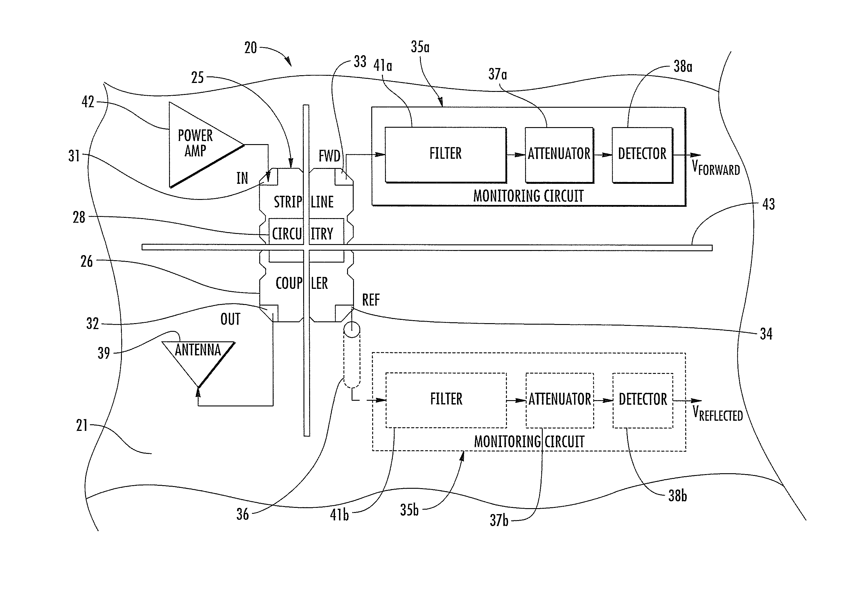
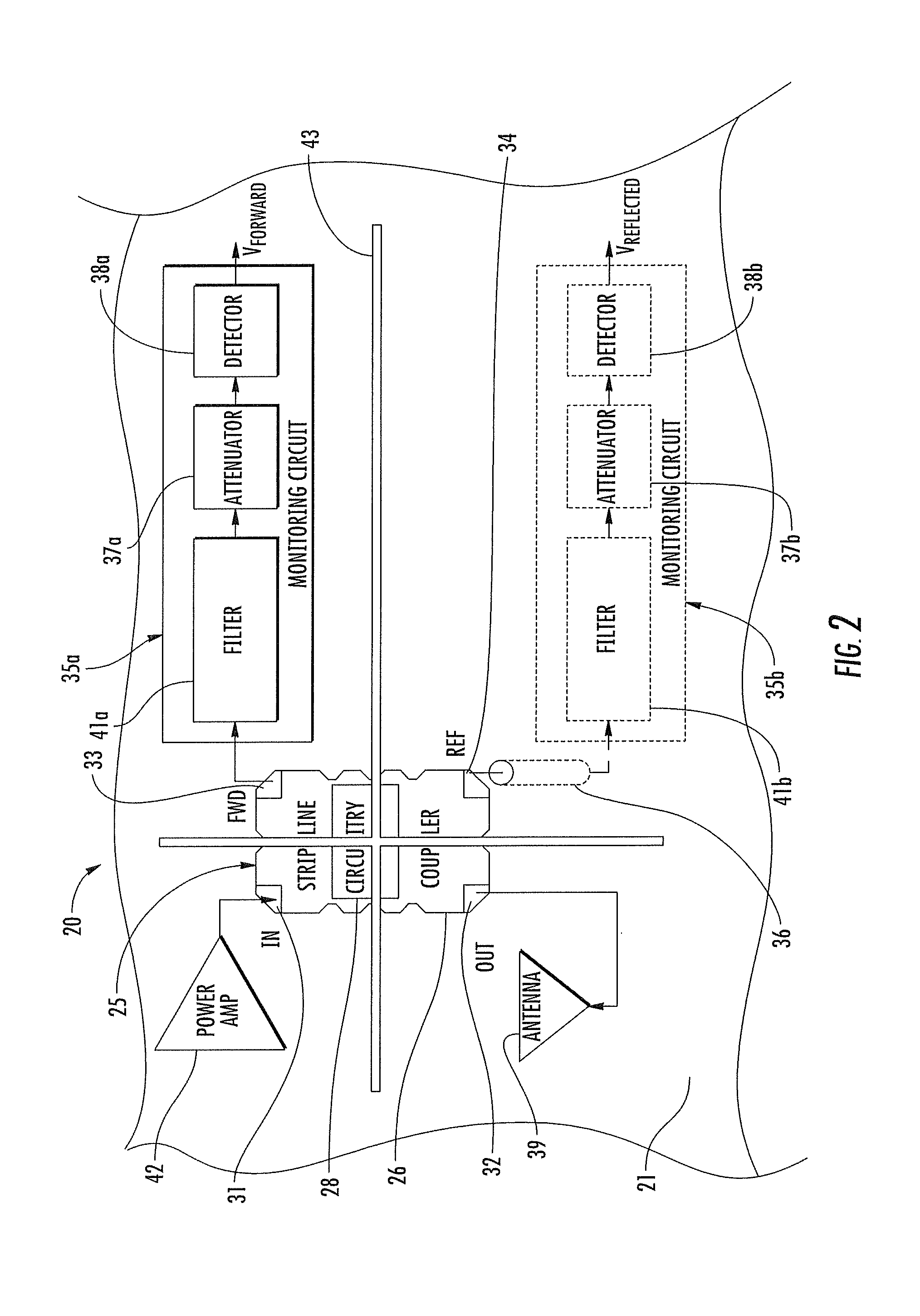
[0025]Referring initially to FIGS. 2 and 3, the electronic device 20 illustratively includes a printed circuit board 21 (PCB) including a ground plane 22 sandwiched between two dielectric layers 29a, 29b and having first and second opposing surfaces 23, 24. The ground plane 22 may be a metallic layer within the PCB 21 (FIG. 3), or may be a metallic layer carried by either the first or second opposing surfaces 23, 24. Other ground plane 22 arrangements will...


PUM


Abstract

An electronic device may include a printed circuit board (PCB) including a ground plane and having first and second opposing surfaces. The electronic device may also include a radio frequency (RF) directional coupler carried by the first surface of the PCB and including a housing and circuitry therein defining an input port, an output port, and first and second monitoring ports. A first monitoring circuit may be carried by the first surface of the PCB and connected to the first monitoring port. The electronic device may also include a via conductor connected to the second monitoring port and extending through the PCB to the second surface thereof. A second monitoring circuit may also be carried by the second surface of the PCB and connected to the via conductor.

Description

FIELD OF THE INVENTION[0001]The present invention relates to the field of communications and, more particularly, to radio frequency couplers and related methods.BACKGROUND OF THE INVENTION[0002]A typical broadband power amplifier may include a radio frequency (RF) directional coupler. For example, a typical broadband power amplifier may be a multi-octave power amplifier that generally needs a broadband, multi-octave RF directional coupler for transmitter gain control (TGC). The broadband, multi-octave RF directional coupler may also be needed for voltage standing wave ratio (VSWR) detection, and receive (RX) protect detection. For example, a power amplifier covering a frequency range of about 225-2000 MHz covers operating bands where both very high frequency (VHF) and microwave design techniques may be used. However, neither a VHF nor a microwave approach may be sufficient for the overall desired operating band.[0003]For example, a prior art system, as illustrated in FIG. 1, include...

Claims


Application Information

Patent Timeline
Patent Type & Authority Patents(United States)
IPC IPC(8): H01P5/12H01P1/22
CPCH01P5/18H04B1/52H05K1/0243H05K2201/10545H05K2201/1006
Inventor MCINTYRE, JOHN ROBERTMANICONE, ANTHONY CLEMENT
Owner HARRIS GLOBAL COMM INC
Why Eureka
Try Eureka