
Low profile cutting assembly with a return spring

a low-profile cutting and spring technology, applied in the field of surgical instruments, can solve the problems of relatively ineffective electrosurgical procedures and contribute to imprecise tissue separation, and achieve the effect of facilitating the spring element actuation

Active Publication Date: 2012-04-24
TYCO HEALTHCARE GRP LP
View PDF67 Cites 881 Cited by
  • Summary
  • Abstract
  • Description
  • Claims
  • Application Information

AI Technical Summary

Benefits of technology

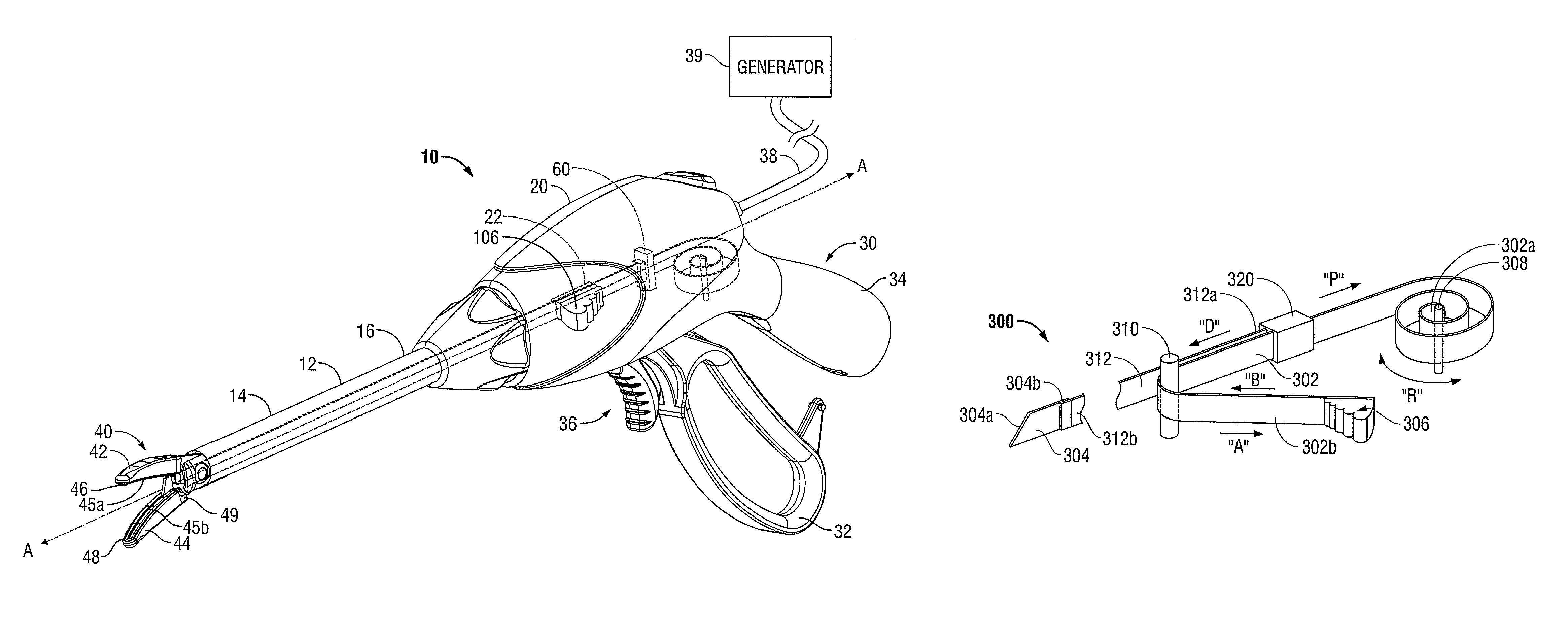
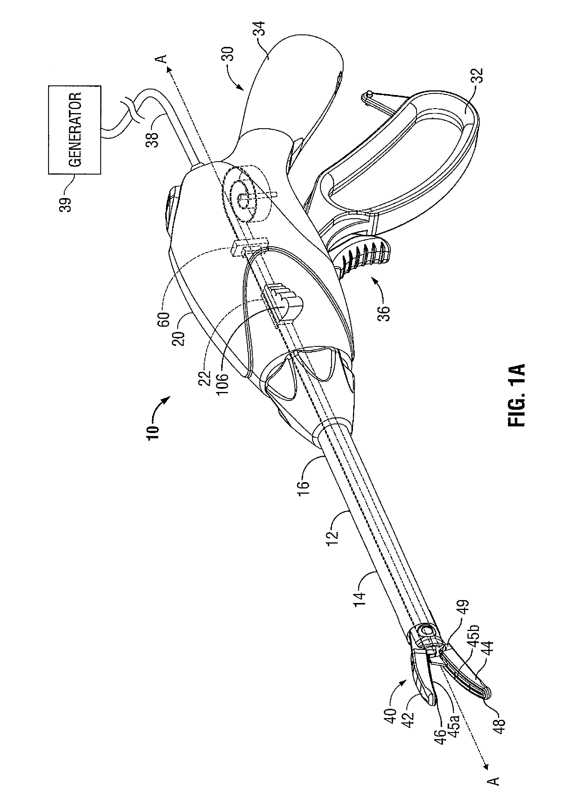
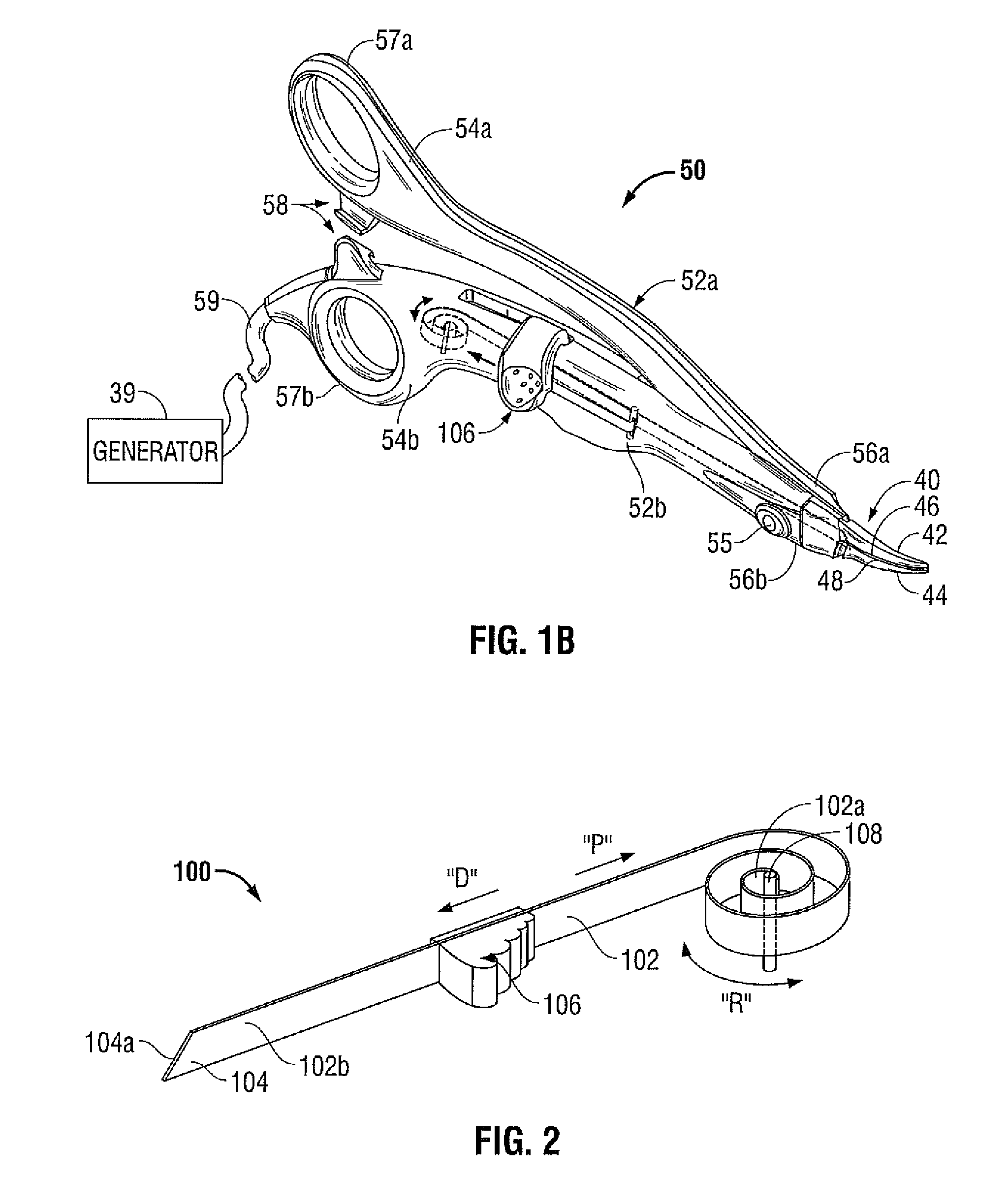
The present disclosure relates to a forceps that includes a housing, a cutting assembly, and an actuator. The cutting assembly includes a spring element with proximal and distal ends, a joining member, and a cutting element. The spring element is fixed to a boss within the housing and is coiled at a proximal end to create a spring bias against the boss. The actuator is operably coupled to the spring element and is configured to selectively advance the cutting edge of the spring element against the bias to sever tissue disposed between the jaw members. The forceps may also include stops and bumpers to limit movement of the spring element and ensure precise cutting. A guide pin may be disposed within the housing to support the spring element and facilitate actuation against the bias. The technical effects of the present disclosure include improved precision and control in tissue cutting with the forceps.

Problems solved by technology

As can be appreciated, this additional step may be both time consuming (particularly when treating multiple operative sites) and may contribute to imprecise separation of the tissue due to the misalignment or misplacement of the severing instrument along the previously electrosurgically treated tissue.
Other instruments include blade members or shearing members which simply cut tissue in a mechanical and / or electromechanical manner and are relatively ineffective for electrosurgical procedures.

Method used


Image

  • Low profile cutting assembly with a return spring
  • Low profile cutting assembly with a return spring
  • Low profile cutting assembly with a return spring

Examples


Embodiment Construction

[0019]Embodiments of the presently-disclosed electrosurgical instrument are described in detail with reference to the drawings wherein like reference numerals identify similar or identical elements. As used herein, the term “distal” refers to that portion which is further from a user while the term “proximal” refers to that portion which is closer to a user.

[0020]In general, the present disclosure relates to a cutting assembly that is utilized in conjunction with surgical instruments. The cutting assembly may include a constant force spring element and a cutting element that defines a cutting edge at a distal end thereof. The constant force spring element includes fixed and movable ends. The fixed end of the spring element is configured in a biasing coiled configuration. During use, the movable end is selectively moved from a first position to a second position in order to cut tissue. After a successful cut has been performed, the movable end of the spring element is selectively rel...


PUM


Abstract

A forceps that includes a housing, a cutting assembly, and an actuator. The housing has a shaft attached thereto that extends therefrom and is configured to support a pair of jaw members at a distal end thereof. The jaw members are movable to grasp tissue therebetween. The cutting assembly includes a spring element that has proximal and distal ends. The proximal end of the spring element is fixed to a boss disposed within the housing and the distal end of the spring element includes a cutting edge. The spring element is coiled at a proximal end thereof to create a spring bias against the boss. The actuator is operably coupled to the spring element and is configured to selectively advance the cutting edge of the spring element into the jaw members against the spring bias to sever tissue disposed therebetween.

Description

BACKGROUND[0001]1. Technical Field[0002]The present disclosure relates to surgical instruments. More particularly, the present disclosure relates to surgical instruments having sealing and cutting capabilities.[0003]2. Description of Related Art[0004]During a typical surgical procedure, for example, an open or endoscopic electrosurgical procedure, a clinician may in certain circumstances have to remove an electrosurgical instrument from an operative site, substitute a new instrument, and accurately sever a vessel, which was previously electrosurgically treated. As can be appreciated, this additional step may be both time consuming (particularly when treating multiple operative sites) and may contribute to imprecise separation of the tissue due to the misalignment or misplacement of the severing instrument along the previously electrosurgically treated tissue.[0005]Many surgical instruments have been designed which incorporate a knife or blade member that effectively severs the tissu...

Claims


Application Information

Patent Timeline
Patent Type & Authority Patents(United States)
IPC IPC(8): A61B17/32
CPCA61B17/285A61B17/295A61B18/1442A61B18/1445A61B2017/2945A61B2018/00404A61B2018/00601A61B2018/0063A61B2018/1412A61B2018/1432A61B2018/1455A61B2090/064A61B2090/0807
Inventor RESCHKE, ARLEN J.JOSEPH, DANIEL A.ROMERO, PAUL R.
Owner TYCO HEALTHCARE GRP LP
Learn More