Cab for construction machine

a construction machine and cab technology, applied in the direction of mechanical controls, roofs, doors, etc., can solve the problems of reducing the room space of the operator, the gap between the door and the wall is small, etc., and achieve the effect of reducing the width of the opening of the cab

Active Publication Date: 2012-04-24
KOMATSU LTD
View PDF23 Cites 3 Cited by
  • Summary
  • Abstract
  • Description
  • Claims
  • Application Information

AI Technical Summary

Benefits of technology

[0009]According to the cab for a construction machine, the cut-out portions are arranged in the outer side surfaces of the door and the side wall of the cab. The double-shaft hinges are attached to eliminate or minimize the protrusion of the attachment members of the hinges from the exterior surface of the cab.
[0010]According to this construction, when the door opens / closes the wall, the interposed member pivots with respect to the first member, and the second member additionally pivots with respect to the interposed member. In addition, the first and second members can be fastened to the first and second cut-out portion, which are formed on the wall and the door, respectively. Thus, it is possible to avoid that the hinges protrude from the cab outer peripheral surface. As a result, it is possible to avoid that the hinge structure causes problems that the cab does not meet transportation regulation and the like. In addition, it is possible to improve the outward appearance of the cab.
[0012]According to this construction, the hinges can be attached to eliminate or minimize the protrusion of the outer peripheral surface of the first pivot shaft from the exterior surface of the wall when the door is closed.
[0017]According to this construction, since the width of the coupling part of the interposed member is thus specified, it is possible to surely provide an appropriately large gap between the door and wall when the door is fully opened. Therefore, it is possible to prevent that operator's fingers or the like may be caught in the gap.
[0023]According to this construction, since the second pivot shaft is arranged on the end of the door, the end of the door does not protrude in the doorway of the cab and does not reduce the width of the opening of the cab when the door is fully opened. Since the first pivot shaft is arranged at the position corresponding to the width of the interposed member from the end of the wall, even if the width of the interposed member is substantially reduced, an unnecessary clearance is not produced between the door and the wall.

Problems solved by technology

However, from viewpoint measures against transportation regulation and outward appearance, it is not preferable that the pivot shaft of the hinge protrude from the surface of the door or the wall.
However, if the thickness of the door is large, when the door swings 180 degrees to be opened, the gap between the door and the wall will be small.
For this reason, such a large thickness of the door requires space on the room side, and will reduce operator's room space.

Method used


Image

  • Cab for construction machine
  • Cab for construction machine
  • Cab for construction machine

Examples


first embodiment

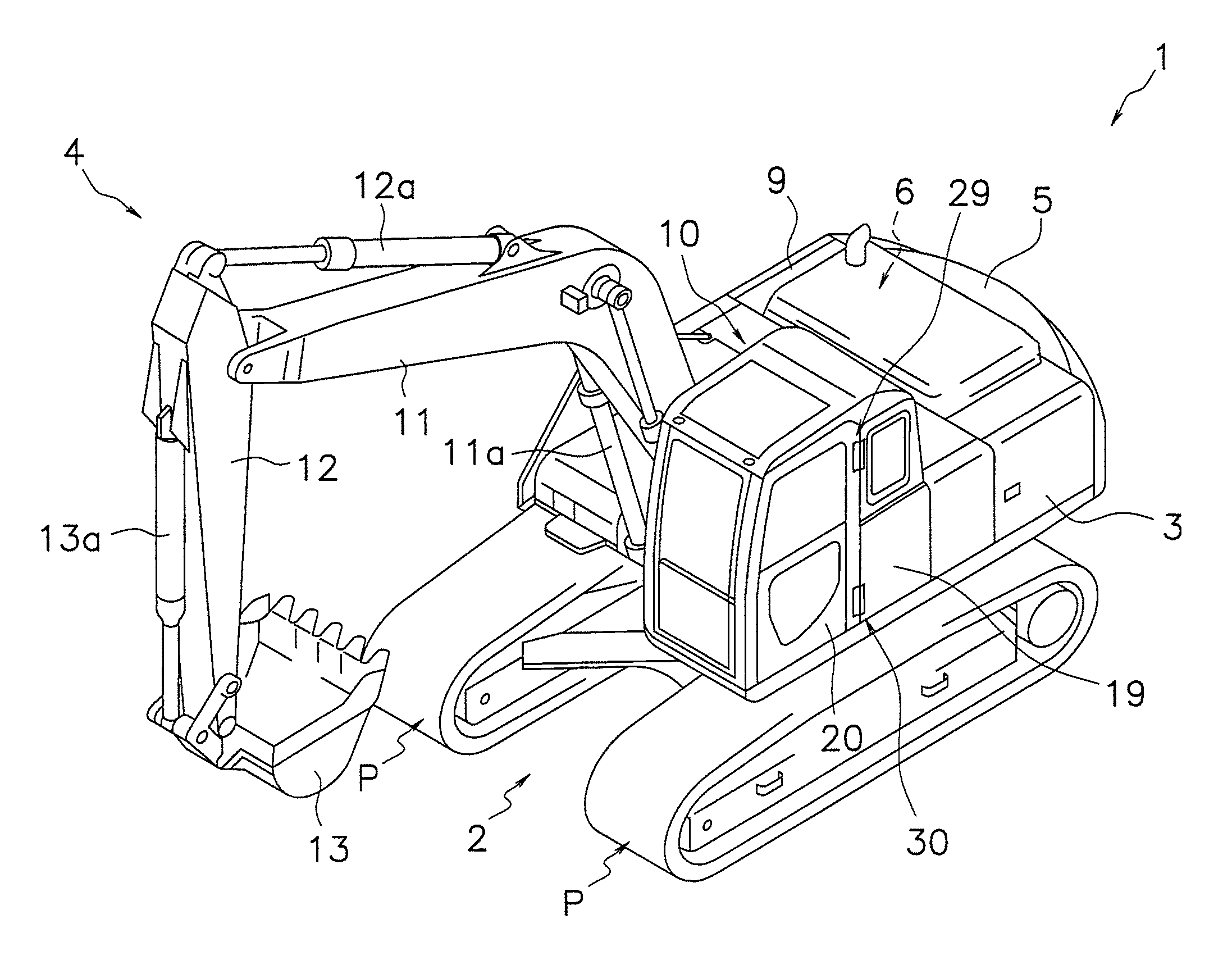
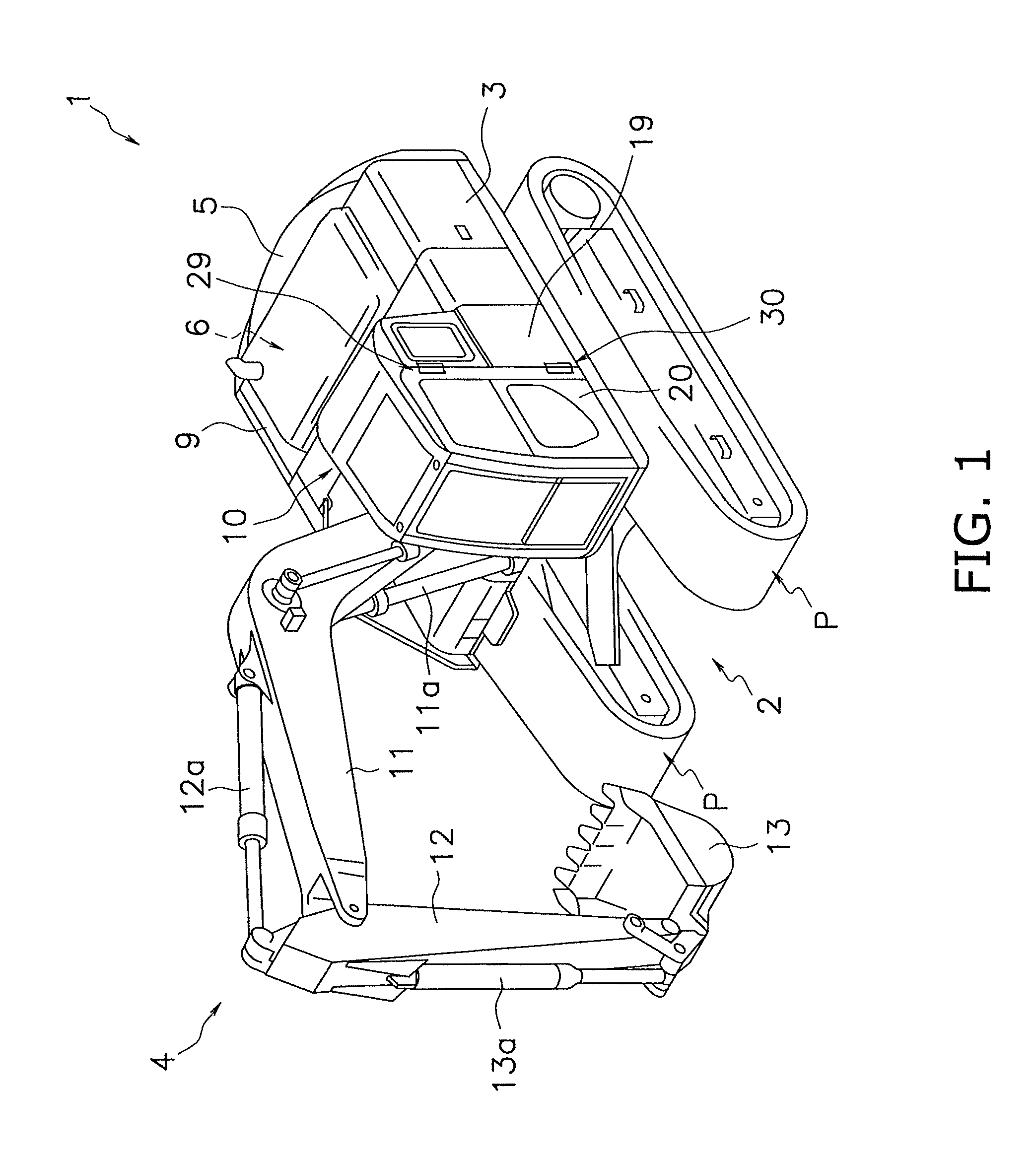
[0048]With reference to FIG. 1, the following description will describe a hydraulic excavator 1 that includes a cab for a construction machine to which a hinge structure according to one embodiment of the present invention is adopted.

Overall Construction of Hydraulic Excavator 1

[0049]The hydraulic excavator 1 according to this embodiment includes a lower traveling unit 2, a revolving base 3, a working unit 4, a counterweight 5, an engine room 6, an equipment compartment 9, and a cab 10, as shown in FIG. 1.

[0050]The lower traveling unit 2 drives crawler belts P that are wounded on the left and right sides of the lower traveling unit 2 relative to the advance direction so that the hydraulic excavator 1 travels frontward and rearward. The revolving base 3 is revolvably mounted on the upper part of the lower traveling unit 2.

[0051]The revolving base 3 can revolve in either direction on the lower traveling unit 2. The working unit 4, the counterweight 5, the engine 6, and the cab 10 are ...

referential example

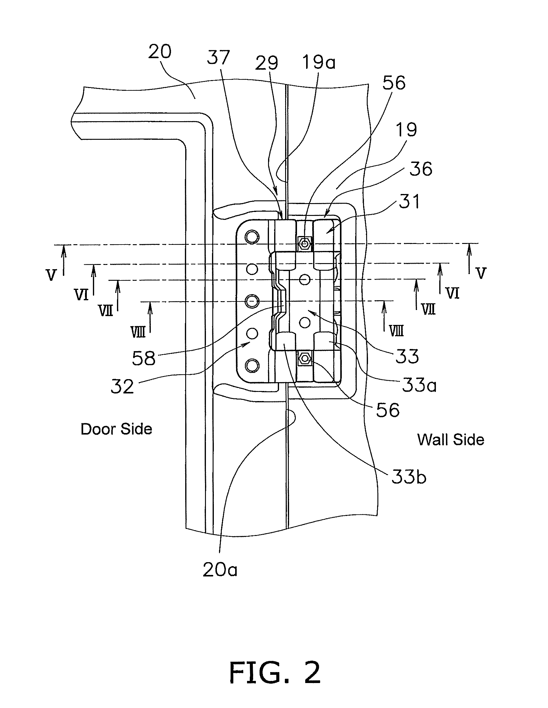
[0113]In the case where double-shaft hinges are used, if the pivot angles are not regulated when the door is fully opened 180 degrees from the closed position, positioning of the striker relative to the engaging member of the wall may be unstable. For this reason, there is a possibility that the striker of the door cannot engage with the engaging member of the wall at a certain position.

[0114]FIG. 14 is a schematic view showing an opening / closing structure of a door that includes the double-shaft hinges.

[0115]The double-shaft hinge 133 includes a first pivot shaft 136 that is arranged in a side wall 119 of a machine, and a second pivot shaft 137 that is arranged in the end of a door 120. A striker 127 is arranged on the door 120. It is expected that, when the door 120 is opened about 180 degrees from the closed position and is orientated in parallel to the side wall 119, the striker 127 is positioned at the position where the striker 127 can engage with the engagement member 126.

[01...


PUM


Abstract

A cab for a construction machine includes hinges that swingably mount the door to the wall. Each of the hinges includes a first member secured to a first cut-out portion of the wall, a second member secured to a second cut-out portion of the door, an interposed member interposed between the first and second members, and first and second pivot shafts pivotally respectively coupling the first and second members to the interposed member. The cab further includes first and second stoppers that regulate first and second angles of the interposed member with respect to the first and second members, respectively, and a bolt member arranged in the second stopper to move in its axial direction to adjust the second angle. An imaginary surface corresponding to an outermost part of each of the hinges is substantially coplanar with exterior surfaces of the wall and the door, when the door is closed.

Description

CROSS-REFERENCE TO RELATED APPLICATIONS[0001]This national phase application claims priority to Japanese Patent Application No. 2008-279412 filed on Oct. 30, 2008. The entire disclosure of Japanese Patent Application No. 2008-279412 is hereby incorporated herein by reference.TECHNICAL FIELD[0002]The present invention relates to a cab for a construction machine that includes hinges for mounting a door to a wall so that the door can be opened 180 degrees.BACKGROUND ART[0003]In construction machines such as hydraulic excavator, a work is occasionally conducted with the door is fully opened 180 degrees. For this reason, it is necessary that the door in construction machines be constructed to swing 180 degrees. However, in the case where single-shaft hinges are used to allow the door to swing 180 degrees, the pivot shafts of the hinges protrude from the surface of the door or a wall (see Japanese Patent Laid-Open Publication No. 2006-57245).[0004]On the other hand, Japanese Patent Laid-O...

Claims


Application Information

Patent Timeline
Patent Type & Authority Patents(United States)
IPC IPC(8): B60N99/00
CPCB60J5/0487E02F9/00E02F9/0891E02F9/163E05C3/24E05C17/50E05D3/127E05B53/003E05D11/06E05Y2900/518E05Y2900/531Y10T16/547E02F9/16B60J5/00B60J5/04E05D3/06
Inventor NAMURA, AKIHIDESUGIMOTO, HIROKAZUTSUJI, KOUDOU
Owner KOMATSU LTD
Why Eureka
Try Eureka