
Pre-rounding element on a rounding apparatus

a technology of rounding apparatus and pre-rounding element, which is applied in the direction of curved planar seam welding, soldering auxiliary devices, domestic vessels, etc., can solve the problems of shortfall cost of machine operator, and lower efficiency of rounding apparatus and subsequent steps, so as to achieve good and uniform rounding and simple construction

Active Publication Date: 2012-04-17
SOUDRONIC
View PDF6 Cites 2 Cited by
  • Summary
  • Abstract
  • Description
  • Claims
  • Application Information

AI Technical Summary

Benefits of technology

[0007]This permits a change of the impact of the metal sheet to be rounded during operation and at the same time keeps the adjusted influence on the metal sheet constant.
[0008]The pre-rounding element or rounding element has a solid body joint, thus resulting in a simple construction. The solid body joint works in a play-free and wear-free way. Thereby, the solid body joint is formed in such a way, that a mostly uniform deflection by the actuating member results. This results in a uniform influence of the element on the metal sheet and therefore in a good and uniform rounding result.
[0009]According to a further aspect of the invention, the pre-rounding element or the rounding element is constructed by means of the claimed features in such a way, that its lower part is deformed as little as possible during its influence on the metal sheet. This results in a more uniform influence of the element on the metal sheet and therefore in a good and uniform rounding result.

Problems solved by technology

Because thereby not all of the frames rounded in series are located at the same position within the rounding station and they have different rounding diameters, this may result in variations of the degree of overlapping in the welding station, which is problematic for the welding of the body, or it may lead to problems during the lateral pushing of the bodies out of the rounding machine and into the welding installation and therefore to a machine stop with long downtimes. The efficiency of the machine is thereby reduced and shortfall costs arise for the machine operator.
The rounding has to be often checked and the rounding system, particularly the pre-rounding wedge, has to be readjusted if necessary, wherein this has to be done during the idle time, thus resulting in a lower efficiency of the rounding apparatus and of subsequent steps and in shortfall costs for the machine operator.

Method used


Image

  • Pre-rounding element on a rounding apparatus
  • Pre-rounding element on a rounding apparatus
  • Pre-rounding element on a rounding apparatus

Examples


Embodiment Construction

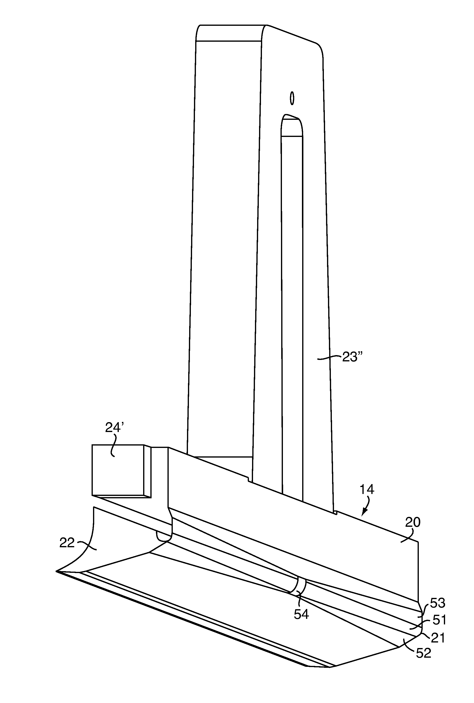
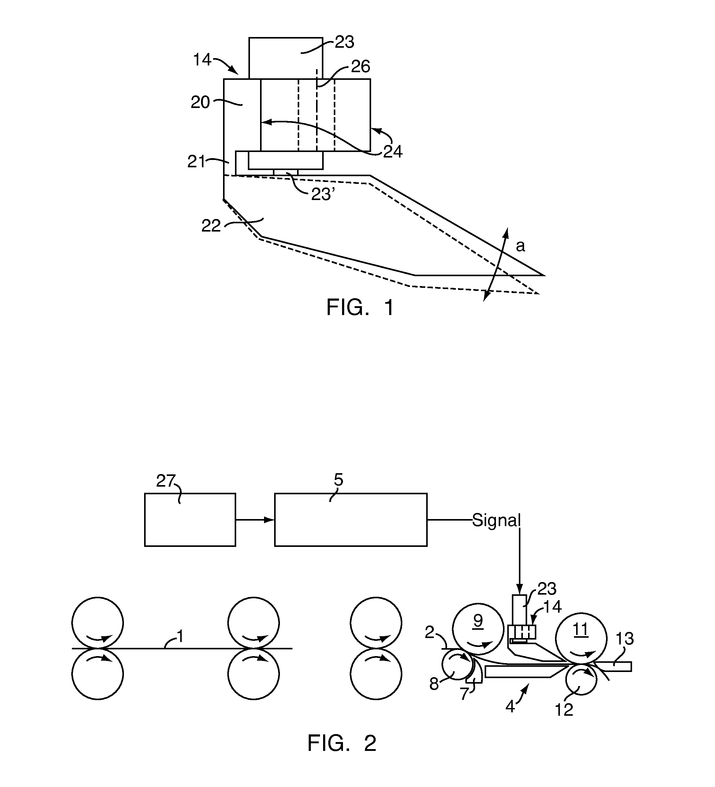
[0020]FIG. 1 shows in a side view a pre-rounding element 14. Its operation within a rounding apparatus 4 is shown schematically in FIG. 2. The rounding element 13 of the rounding apparatus 4 may be executed according to the aspects of the invention as well. In the following examples they will be explained by means of a pre-rounding element, however the corresponding execution and use as rounding element is included therein as well.

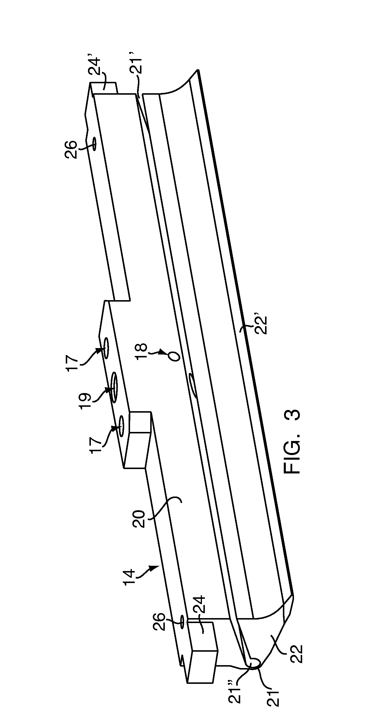
[0021]The pre-rounding element 14, which is a pre-rounding wedge in the shown embodiment, because its lower part 22 which acts upon the respective metal sheet is wedge-shaped in its front section, has a rigid or, during operation, fixed upper element part 20 respectively. In this embodiment, it is a part 20 which is executed to be fixed at a machine part of the rounding apparatus, in the shown example having attachment means on both sides, for example bores 26 and guides 24, which allow an attachment to the rounding apparatus and a vertical base setting to...


PUM

PropertyMeasurementUnit
speedaaaaaaaaaa
section moduliaaaaaaaaaa
section modulusaaaaaaaaaa

Abstract

When rounding metal sheet sections for forming can bodies by means of a rounding machine, a pre-rounding element is used, whose lower part is deflectable with respect to the upper part by means of an actuating element. Thereby, the joint between the upper and the lower part is executed as a solid body joint whose section modulus in bending during the deflection is different along the joint. Thereby, a uniform impact on the metal sheet may be reached. Furthermore, the separating gap between the upper and the lower part is arranged obliquely, thus reducing the bending of the lower part.

Description

CROSS REFERENCE TO RELATED APPLICATIONS[0001]This application claims the priority of Swiss patent application 1929 / 08, filed Dec. 9, 2008, the disclosure of which is incorporated herein by reference in its entirety.BACKGROUND[0002]The invention is related to a pre-rounding element or a rounding element in a rounding apparatus, a rounding apparatus with such a pre-rounding element or a rounding element, as well as a welding device for can bodies with such a rounding apparatus.PRIOR ART[0003]Rounding apparatuses are used in the manufacturing of container bodies, particularly can bodies, made of metal sheet. For this, after the rounding, the container body blanks are transported directly into a welding machine for the welding of the longitudinal seam of the body. Thereby, the destacking of the metal sheets, the rounding apparatus and the welding machine normally form an entity. Corresponding systems for the production of cans are for example known from DE-A-33 30 171 or from U.S. Pat. ...

Claims


Application Information

Patent Timeline
Patent Type & Authority Patents(United States)
IPC IPC(8): B21D51/28B23K37/00
CPCB21D5/14B23K11/066B21D51/2676B23K2201/125B23K2101/125
Inventor HUG, PETERBOISSIN, GUYSCHULTHESS, OLIVER
Owner SOUDRONIC
Learn More