
Inertial measurement unit for spin-stabilized aerial vehicles, and method of providing guidance information using same

a technology of aerial vehicles and measurement units, applied in acceleration measurement in multiple dimensions, instruments, navigation instruments, etc., can solve the problems of random components, time-consuming and expensive testing, relative instability, etc., and achieve the effect of removing the bias of their signals and ensuring accuracy and precision

Inactive Publication Date: 2012-04-17
MILLI SENSOR & ACTUATOR SYST
View PDF10 Cites 24 Cited by
  • Summary
  • Abstract
  • Description
  • Claims
  • Application Information

AI Technical Summary

Benefits of technology

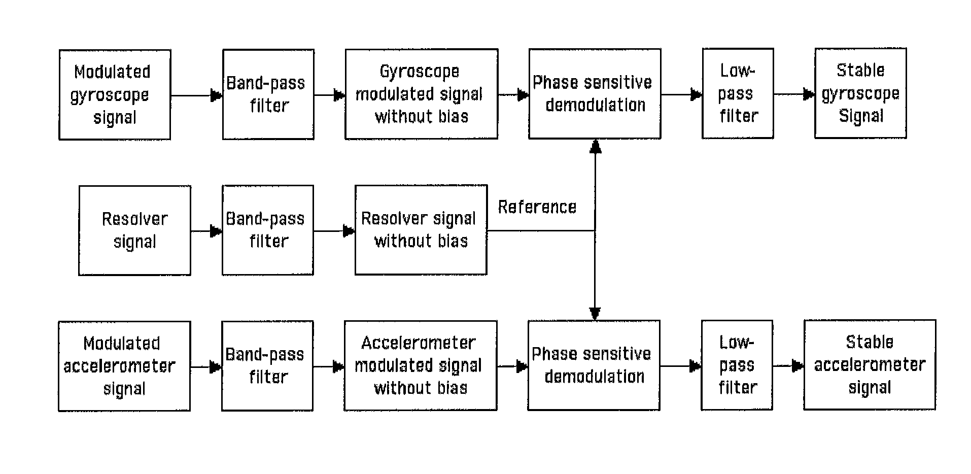
[0009]The invention includes the use of a MEMS IMU to a spin-stabilized rocket (or any other spinning body whose orientation / attitude and / or acceleration needs to be sensed) and to take advantage of the available spin to spin-stabilize the X, Y gyroscope and accelerometer instruments; that is, to remove the bias from their signals and to do it without an expensive carousel. The bias stabilized instruments will further achieve performance improvement for greater accuracy and precision.
[0010]An advantage to the spinning vehicle is that MEMS instruments will operate under the spin and the improved performance enables the replacement of more expensive, larger instruments that may require de-spinning hardware. A related advantage is the reduced weight and reduction in required fuel.
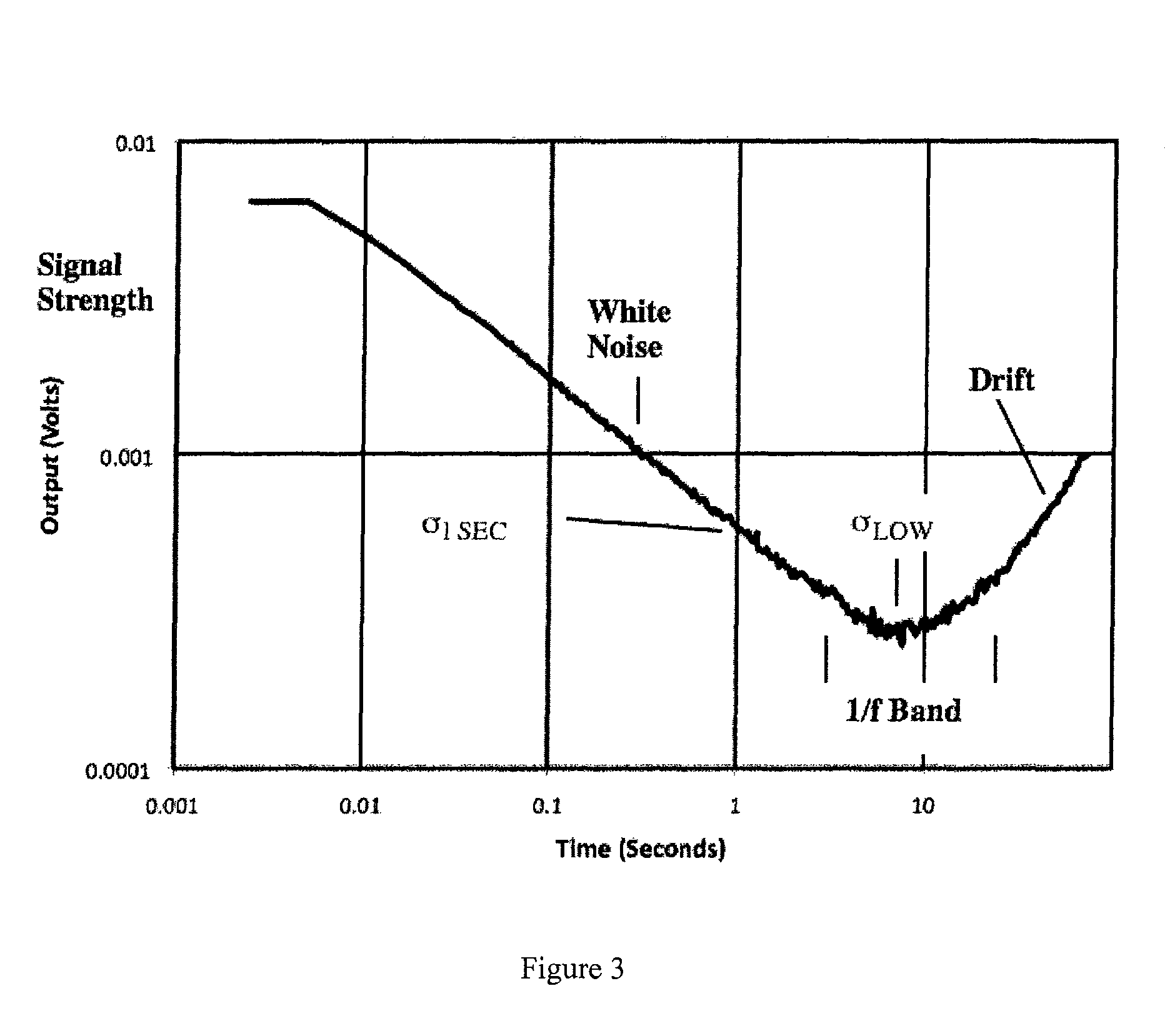
[0017]This invention also relates to the improvement of bias instability and best resolution performance of the X, Y gyroscopes and accelerometers.

Problems solved by technology

Due to their very small size, and materials and methods of construction, such MEMS inertial instruments are relatively sensitive to ambient temperature and other environmental factors, such as shock, vibration and acoustics.
These sensitivities make them relatively unstable.
This testing is time consuming and expensive, and also may not anticipate every possible condition that the instrument may be exposed to, which can lead to errors.
Random components can be traced to a cause but cannot be controlled.
The problem is that under motion, the instrument bias is undistinguishable from the signal generated by the motion, hence the output is incorrect and the MEMS instrument is impractical and requires continuous correction to be useful.
In particular for MEMS instruments, which have low signals, the 1 / f instability is relatively high.

Method used


Image

  • Inertial measurement unit for spin-stabilized aerial vehicles, and method of providing guidance information using same
  • Inertial measurement unit for spin-stabilized aerial vehicles, and method of providing guidance information using same
  • Inertial measurement unit for spin-stabilized aerial vehicles, and method of providing guidance information using same

Examples


Embodiment Construction

Introduction

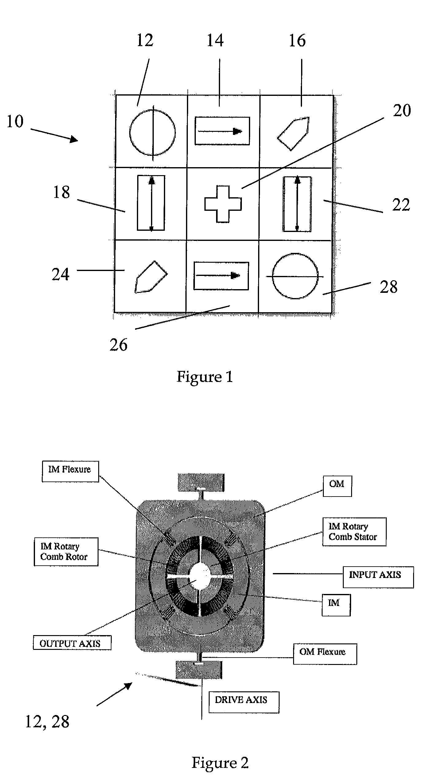
[0050]Spin-stabilized rockets and munitions require attitude information relative to the Earth for guidance and navigation purposes. The IMU gyro instruments measure rotation rates about the Pitch, Roll and Yaw Axes (the effective body axes that do not spin with the vehicle) which can be related to inertial axes. The IMU accelerometer instruments measure acceleration along the same axes.

[0051]MEMS IMU instruments by themselves are not sufficiently stable for applications where external inputs such as GPS are not available. Much of the instability is due to bias which changes with time and cannot be distinguished from the instrument signals. The spin-modulation approach is designed to separate the bias from the signal during flight. For the spinning aerial vehicle application, the spinning vehicle creates the instrument response that has to-date been accomplished with a carousel. An accelerometer that senses the gravity (G)-vector is used to supply information regarding t...


PUM


Abstract

An inertial measurement unit (IMU) for a spinning aerial vehicle that spins about a spin axis having a substrate defining a plane, the substrate fixed to the vehicle with the plane essentially orthogonal to the spin axis so that the substrate spins about the spin axis as the vehicle does, at least one generally planar gyroscope coupled to the substrate, the gyroscope defining a gyro input axis that is essentially parallel to the plane and generating a gyro output signal, at least one generally planar accelerometer coupled to the substrate, the accelerometer defining an accelerometer input axis that is essentially parallel to the plane and generating an accelerometer output signal, and a system for demodulating the gyro output signal with a phase-sensitive demodulation referenced to the accelerometer output signal. Also featured is a method of providing guidance information for a spinning aerial vehicle that spins about a spin axis using the described system.

Description

CROSS REFERENCE TO RELATED APPLICATION[0001]This application claims priority of provisional application Ser. No. 61 / 012,664 filed on Dec. 10, 2007, the entire contents of which are incorporated herein by reference.FIELD OF THE INVENTION[0002]This invention relates to the guidance of spin-stabilized rockets, munitions and other aerial vehicles with a MEMS Inertial Measurement Unit (IMU).BACKGROUND OF THE INVENTION[0003]Micro-electro-mechanical systems (MEMS) gyroscopes and accelerometers, such as disclosed in U.S. Pat. Nos. 6,725,719, 6,859,751 and 7,406,867 (all incorporated herein by reference), are generally planar instruments. Due to their very small size, and materials and methods of construction, such MEMS inertial instruments are relatively sensitive to ambient temperature and other environmental factors, such as shock, vibration and acoustics. These sensitivities make them relatively unstable. Accordingly, it has been necessary to extensively test such instruments under a var...

Claims


Application Information

Patent Timeline
IPC IPC(8): G01P15/00G01C19/00
CPCG01C19/5776G01C21/16G01P15/18G01C21/166G01C21/188
Inventor CARDARELLI, DONATO
Owner MILLI SENSOR & ACTUATOR SYST
Learn More