
Drywall trowel

a drywall and spouting technology, applied in the field of drywall trowels, can solve the problems of inability to widen the swath, the pressure exerted by the conventional corner tool, and the general spread or smoothing of beads, and achieve the effect of smooth spreading of viscous materials

Inactive Publication Date: 2012-04-10
GIANNANTONIO NICHOLAS
View PDF15 Cites 6 Cited by
  • Summary
  • Abstract
  • Description
  • Claims
  • Application Information

AI Technical Summary

Benefits of technology

"The present invention is a hand-held tool made of a flexible sheet material that can be easily attached to a handle. The sheet is bent to form a V-shaped point and a flat surface blade for smoothly spreading viscous materials to joints, corners, and flat surfaces. The tool is made of a lightweight, easy-to-manufacture material. The technical effects of the invention include its ability to smoothly apply viscous materials to irregular surfaces, corners, and flat surfaces without requiring adjustment of the tool. It is also designed to prevent the angle of the blade from spreading further as the material is being applied. Overall, the invention allows for a single operation to create a finished surface."

Problems solved by technology

However, the thin bead is not generally spread or smoothed once it is applied, and because of the thin bead, a wide swath is not possible.
Conventional corner tools do not uniformly distribute pressure exerted by the user.
As a result of this non-uniform pressure distribution, the drywall tape gets caught on the bottom of the tool.
Moreover, this tool can only be used for inside corners.
Except for the very skilled artisan this tool makes the job very time consuming and difficult.
Due to the placement of the handle and the angle at which the tool is configured, it can only be used for outside corners.
Additionally, both of the current inside and outside corner tools are incapable of adding the viscous material to the surfaces prior to spreading.
The problem using this approach is that the sharp edge on the flat surface tool gouges the drywall tape in the corners.
It is also difficult to keep a straight edge in inside corners with this tool.
This additional time increases labor cost and decreases efficiency
Additionally, the locking pin mechanism disrupts the flat edge of the blade preventing its use in flat application scenarios.
The handle, along with the additional bend, does not allow for use in flat surface applications.
Further, the handle prevents the use of the tool for outside edge applications.

Method used


Image

  • Drywall trowel
  • Drywall trowel
  • Drywall trowel

Examples


Embodiment Construction

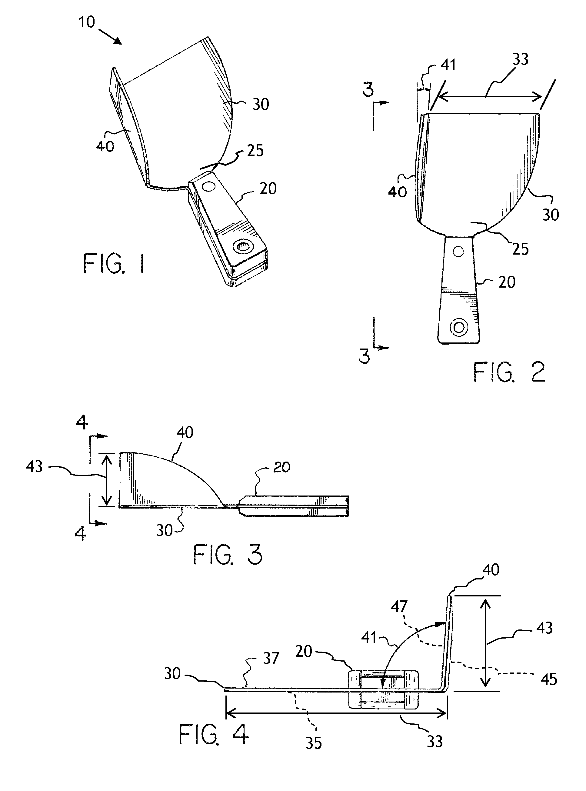
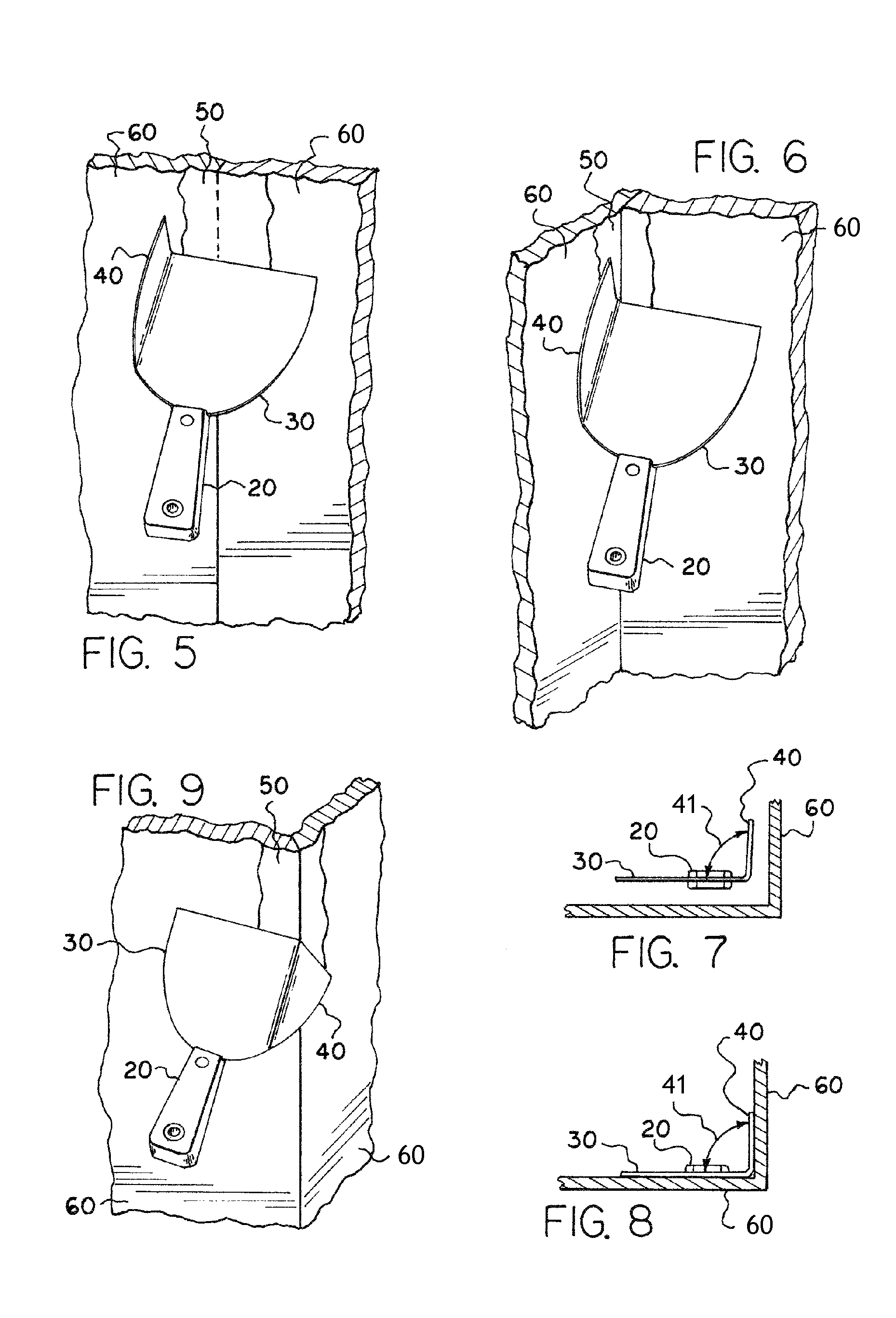
[0029]At the outset, it should be clearly understood that like reference numerals are intended to identify the same structural elements, portions, or surfaces consistently throughout the several drawing figures, as may be further described or explained by the entire written specification of which this detailed description is an integral part. The drawings are intended to be read together with the specification and are to be construed as a portion of the entire “written description” of this invention as required by 35 U.S.C. §112.

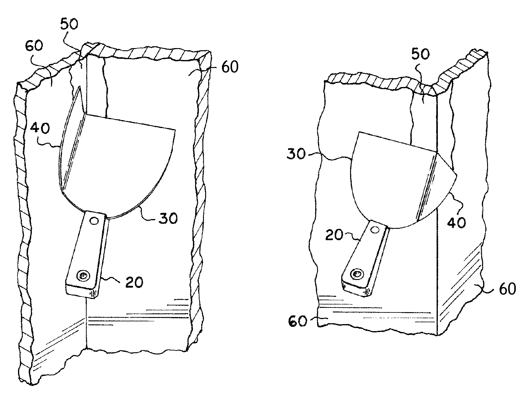
[0030]Traditionally, three separate tools are needed to smooth viscous material used to hide seams, nails or screws and cover corners of the surface area of planar sheets of drywall—one tool for applying viscous material to an inside corner, one for applying material to an outside corner, and a third for applying material along a flat surface. When using conventional tools the viscous material is often applied proportionately unequal. When a person applies v...


PUM

PropertyMeasurementUnit
included angleaaaaaaaaaa

Abstract

A tool for spreading viscous material comprising a sheet of resilient material having a inner face and an outer face, a handle attachment edge and a forward edge. The sheet being bent from the outer face toward the inner face along a bend line to form a V-shaped point to shape an offset corner blade and at least one substantially flat surface blade from the forward edge, and a handle for gripping the tool attached to the handle attachment edge of the sheet distal distally from the bend line.

Description

BACKGROUND OF THE INVENTION[0001]This invention pertains generally to spreading tools for applying viscous materials, particularly to devices for applying viscous materials to a surface efficiently while producing a uniform layer of material, and more particularly to a device for smoothly applying viscous materials along two planar surfaces having a common edge simultaneously with substantially no excess material applied to any surface.[0002]During the building or repair of physical structures, various viscous materials are used to fill and / or seal cracks and gaps in and between structural elements. Examples of viscous materials are caulk, cement, joint compound, spackle, and grout. Numerous tools have been developed to apply the various viscous materials to any number of building materials, such as wood, concrete, sheet rock, drywall, asphalt, cinder, etc. One such style of tool is a caulking-gun which applies a thin bead of material to intersections between one wall and other surf...

Claims


Application Information

Patent Timeline
Patent Type & Authority Patents(United States)
IPC IPC(8): E04F21/16
CPCE04F21/16E04F21/161E04F21/1655
Inventor GIANNANTONIO, NICHOLAS
Owner GIANNANTONIO NICHOLAS
Learn More