
Spark plug

a technology of spark plugs and plugs, applied in the direction of spark plugs, machines/engines, mechanical equipment, etc., can solve the problems of reducing the rigidity of the insulator, easy and application of external force in the bending direction to the spark plug, so as to prevent the generation of cracks or fractures in the insulator, the strength (rigidity) and the strength of the insulator is high

Active Publication Date: 2012-03-27
NGK SPARK PLUG CO LTD
View PDF8 Cites 2 Cited by
  • Summary
  • Abstract
  • Description
  • Claims
  • Application Information

AI Technical Summary

Benefits of technology

[0058]In the spark plug according to Claim 1 of the invention, since the proof strength against the local stress concentration can be increased by adjusting the balance of the size and modulus of section of the insulator, even though the rear end side body portion of the insulator is subjected to the external force in the bending direction perpendicular to the axial direction, the stress that is produced in accordance with the external force is dispersed in the interior thereof, whereby the stress is mitigated. As a result of which the generation of cracks or fractures in the insulator can be prevented. Although this will be described in greater detail below, by regulating the relationship between τA and τB, which will be described later, the balance of strength (rigidity) of the insulator is adjusted.
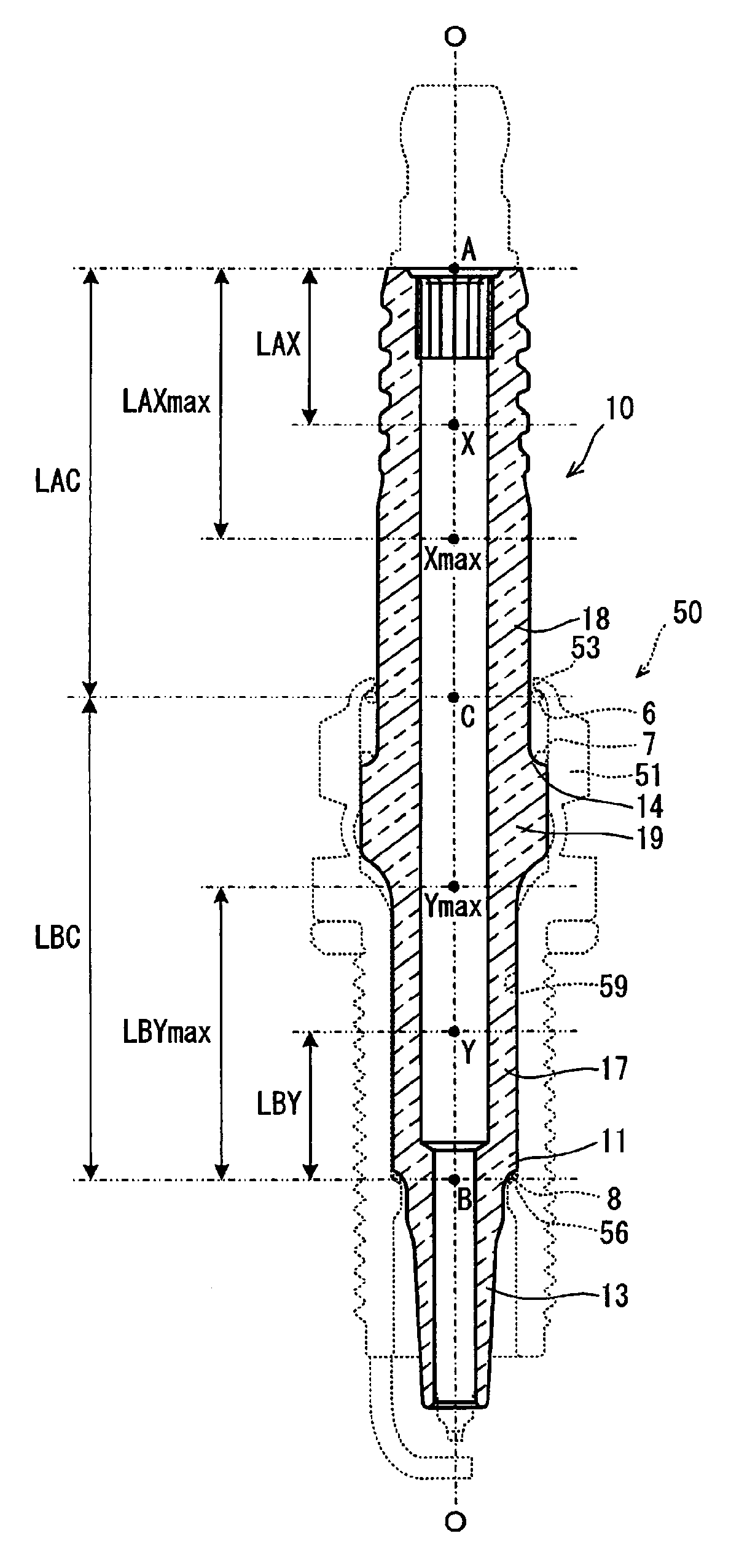
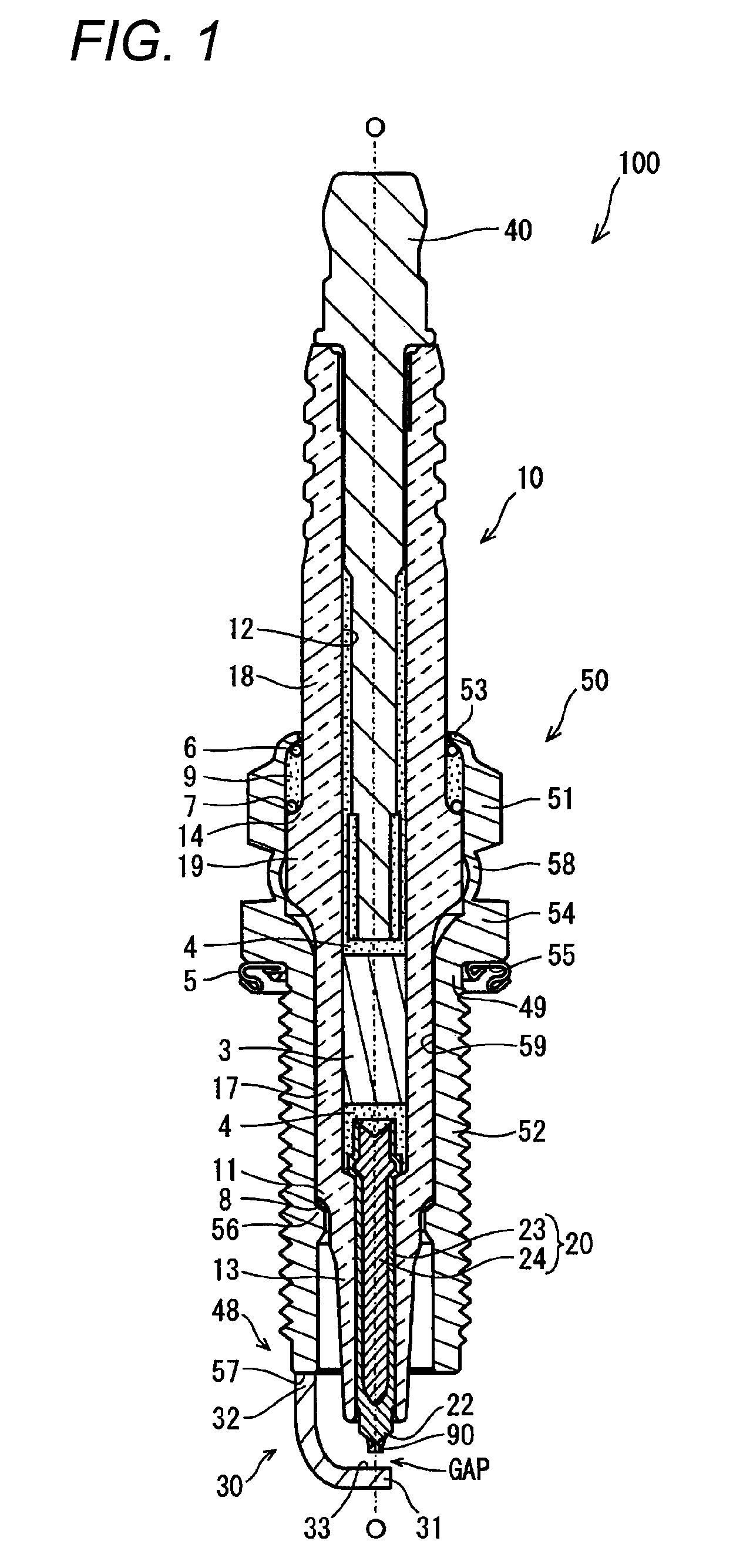
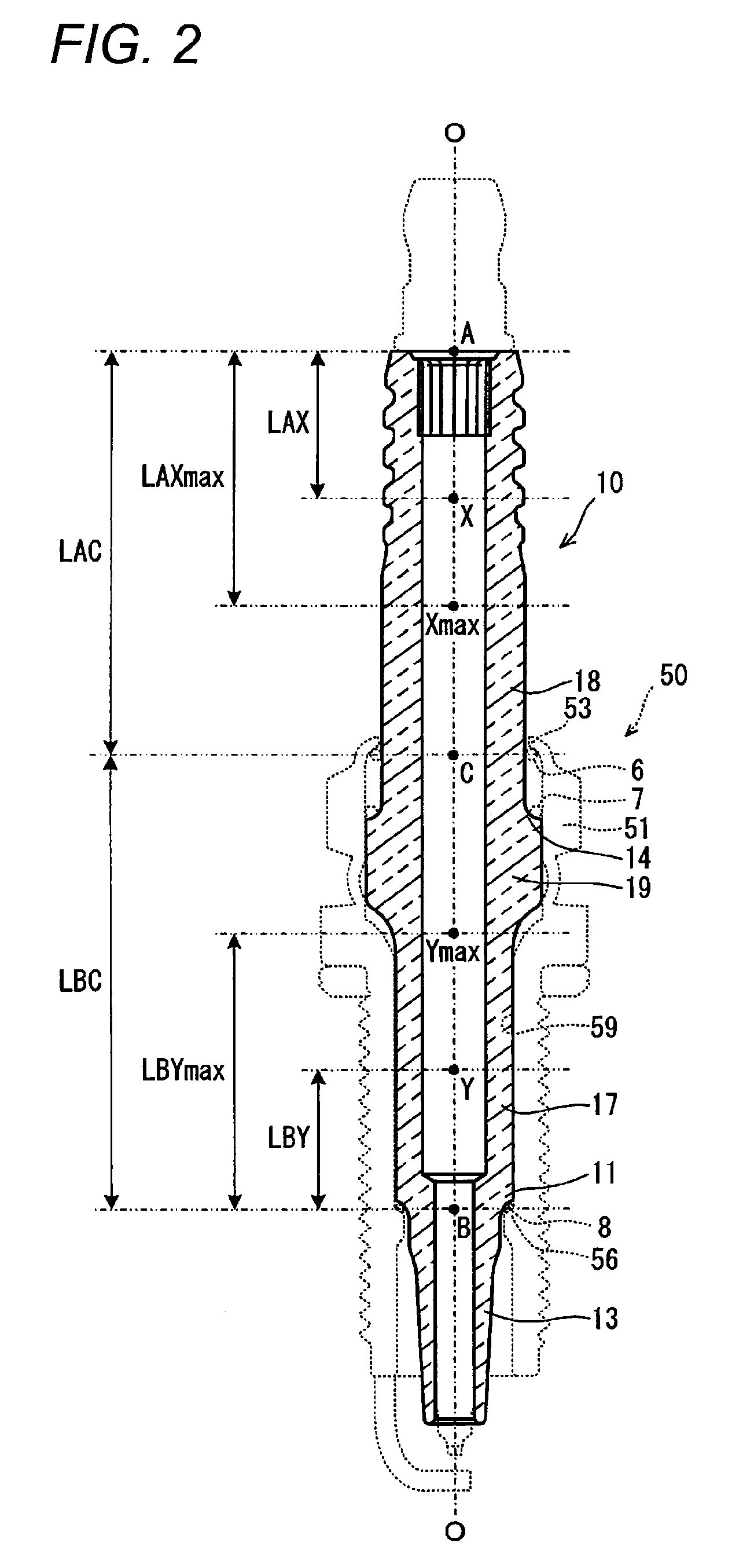
[0059]The insulator is held within the inner hole of the metal shell in such a manner as to be supported by the crimping portion and the ledge portion, via the packing, of the metal shell. Because of this, when the insulator receives the external force in the bending direction perpendicular to the axis at the rear end side body portion thereof, a point of effort is the position received the external force, the supported position of the insulator by the crimping portion which lies closer to the point of effort than the ledge portion (the position C where the crimping portion is brought into contact with the insulator at a rearmost end side) acts as a fulcrum. Then, since the movement of the point of application side is restricted by the supported position of the insulator by the ledge portion (the position B where the packing is brought into contact with the insulator at a frontmost end side), the stress corresponding to the external force received at the point of effort is applied to the portion of the insulator which lies between the position B and the position C.
[0060]Here, τA denotes a proof strength against bending taking place between the point A and the point C of the insulator, and is defined by a position Xmax where the strength (rigidity) of the insulator becomes the lowest between the position A lying at the rear end of the insulator and the position C. As the value of τA is smaller, the strength (rigidity) of the insulator becomes high. In addition, τB denotes a proof strength against a stress applied between the point B and the point C in accordance with bending taking place between the position A and the position C of the insulator, and is defined by a position Ymax where the strength (rigidity) of the insulator becomes the lowest between the position B and the position C. As the value of τB is smaller, the strength (rigidity) of the insulator also becomes high. Consequently, in the event that both the values of τA and τB are small, specifically speaking, both the values are smaller than 0.47, since the insulator originally has a sufficient proof strength against bending, strength balancing adjustment required for dispersion of the stress is not necessary.
[0061]Then, with a view to reducing the diameter of an insulator so as to realize a reduction in size of a spark plug, the invention is intended for an insulator tending to have cracks or fractures due to local stress concentration in the event that a rear end side body portion of the insulator is subjected to an external force in a bending direction, that is, an insulator in which at least either τA or τB takes a value equal to or larger than 0.47. According to the inventor and others, in an insulator in which at least either τA or τB takes a value equal to or larger than 0.47, when paying attention to the relationship between τA and τB (τA / τB) to adjust the balance of strength (rigidity) so as to mitigate the local stress concentration, it has been found that the insulator may be designed, satisfying: 0.71≦τA / τB≦1.27, so as to prevent cracks or fracture of the insulator.
[0062]Also in the spark plug according to Claim 2 of the invention, since the proof strength against the local stress concentration can be increased by adjusting the balance of the size and modulus of section of the insulator, even though the rear end side body portion of the insulator is subjected to the external force in the bending direction perpendicular to the axial direction, the stress produced in accordance with the external is dispersed in the interior thereof, whereby the stress is mitigated. As a result of which the generation of cracks or fractures in the insulator can be prevented. Although this will be described more specifically below, by regulating the relationship between τA and τB, which will be described later, the balance of strength (rigidity) of the insulator is adjusted.
[0063]The insulator used in the spark plug according to the invention set forth in Claim 2 is held within the inner hole in the metal shell in such a manner that the insulator is supported by the crimping portion via the second packing and the ledge portion via the first packing of the metal shell. Because of this, when the insulator receives the external force in the bending direction perpendicular to the axis at the rear end side body portion thereof, a point of effort is the position received the external force, the supported position of the insulator by the crimping portion which lies closer to the point of effort than the ledge portion (the position C where the second packing is brought into contact with the insulator at a rearmost end side) acts as a fulcrum. Then, since the movement of the point of application side is restricted by the supported position of the insulator by the ledge portion (the position B where the first packing is brought into the insulator at a frontmost end side), the stress corresponding to the external force received at the point of effort is applied to the portion of the insulator which lies between the position B and the position C.

Problems solved by technology

When the thickness of the insulator is reduced in association with the reduction in diameter of the spark plug, resulting in a reduction strength (rigidity) of the insulator, in the event that an external force is applied to the insulator in a direction perpendicular to an axial direction (a bending direction), cracks or fractures tend to be generated easily.
There is a possibility that the external force in the bending direction is applied to the spark plug in the event that a mounting tool is brought into collision with a rear end side body portion (an insulator head portion) of the insulator which is exposed from a rear end of the metal shell when the spark plug is mounted in the engine.
When the spark plug is subjected to vibrations generated in association with the driving of the engine in this state, a load due to the weight of the plug cap is generated, leading to a possibility that the external force in the bending direction is applied to the rear end side body portion of the insulator.

Method used


Image

  • Spark plug
  • Spark plug
  • Spark plug

Examples


example 1

[0103]In the evaluation tests, several types of metal shells were prepared which had a nominal diameter of threads of a mounting tread portion of M10 and different lengths in the axis O direction, and insulators having dimensions that enable the insulators to be mounted in the metal shells were designed into 39 types and 14 classifications. Specifically, every insulator was designed so that the length LAC between the position A and the position C became 26 mm when a spark plug was measured after the insulator was mounted in the metal shell. The length LBC between the position B and the position C was made to differ within a range of 25 to 33 mm from insulator to insulator so as to match the types of the metal shells in which the insulators could be mounted. Further, the insulators were designed so that thicknesses of respective portions thereof were made different by, for example, inside diameters of axial holes being made different, so that the test samples have different combinati...


PUM


Abstract

When an insulator of a spark plug receives an external force in a bending direction perpendicular to an axis at a rear end side body portion, a position C where the insulator is supported by a crimping portion via a packing acts as a fulcrum, and a stress is applied between the position C and a position B where the insulator is supported by a ledge portion via a packing. When an insulator is designed in which the balance of size and modulus of section is adjusted so that τA which denotes a proof strength against bending between a rear end position A of the insulator and the position C and τB which denotes a proof strength against bending between the position B and the position C satisfy 0.71≦τA / τB≦1.27, cracks can be prevented.

Description

TECHNICAL FIELD[0001]The present invention relates to a spark plug which is built in an internal combustion engine for igniting an air-fuel mixture.BACKGROUND ART[0002]Conventionally, spark plugs are used in internal combustion engines for ignition. A general spark plug is such that an insulator which holds a center electrode within an axial hole thereof is held by a metal shell so as to surround circumferentially a circumference thereof, so that a spark discharge gap is formed between a ground electrode which is joined to the metal shell and a center electrode. In addition, a spark discharge generated in the spark discharge gap ignites an air-fuel mixture.[0003]In recent years, there are demands on reduction in size and diameter of spark plugs to secure the degree of freedom in designing automotive engines for increase in output and fuel economy thereof, and reductions in diameter and thickness of metal shells and insulators have been attempted. As one of measures taken to achieve ...

Claims


Application Information

Patent Timeline
Patent Type & Authority Patents(United States)
IPC IPC(8): H01T13/00
CPCH01T13/38
Inventor SUZUKI, AKIRAKATO, TOMOAKIMUSASA, MAMORU
Owner NGK SPARK PLUG CO LTD
Learn More