Polymer film splicing method and device, and stretching method
a polymer film and splicing technology, applied in the direction of photosensitive materials, instruments, transportation and packaging, etc., can solve the problems of inability to achieve sufficient splicing strength, inability to stretch the film enough to improve optical properties, and decreased area as a product, so as to facilitate thermal decomposition and prevent the occurrence of wrinkles
- Summary
- Abstract
- Description
- Claims
- Application Information
AI Technical Summary
Benefits of technology
Problems solved by technology
Method used
Image
Examples
embodiment 1
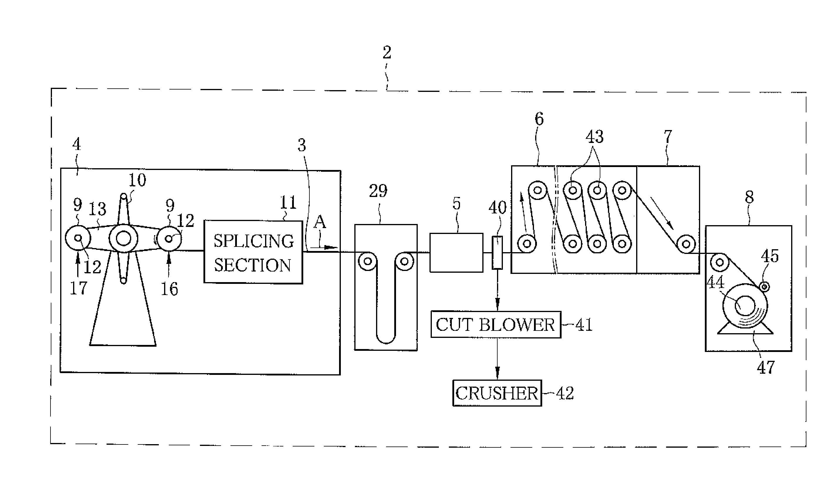
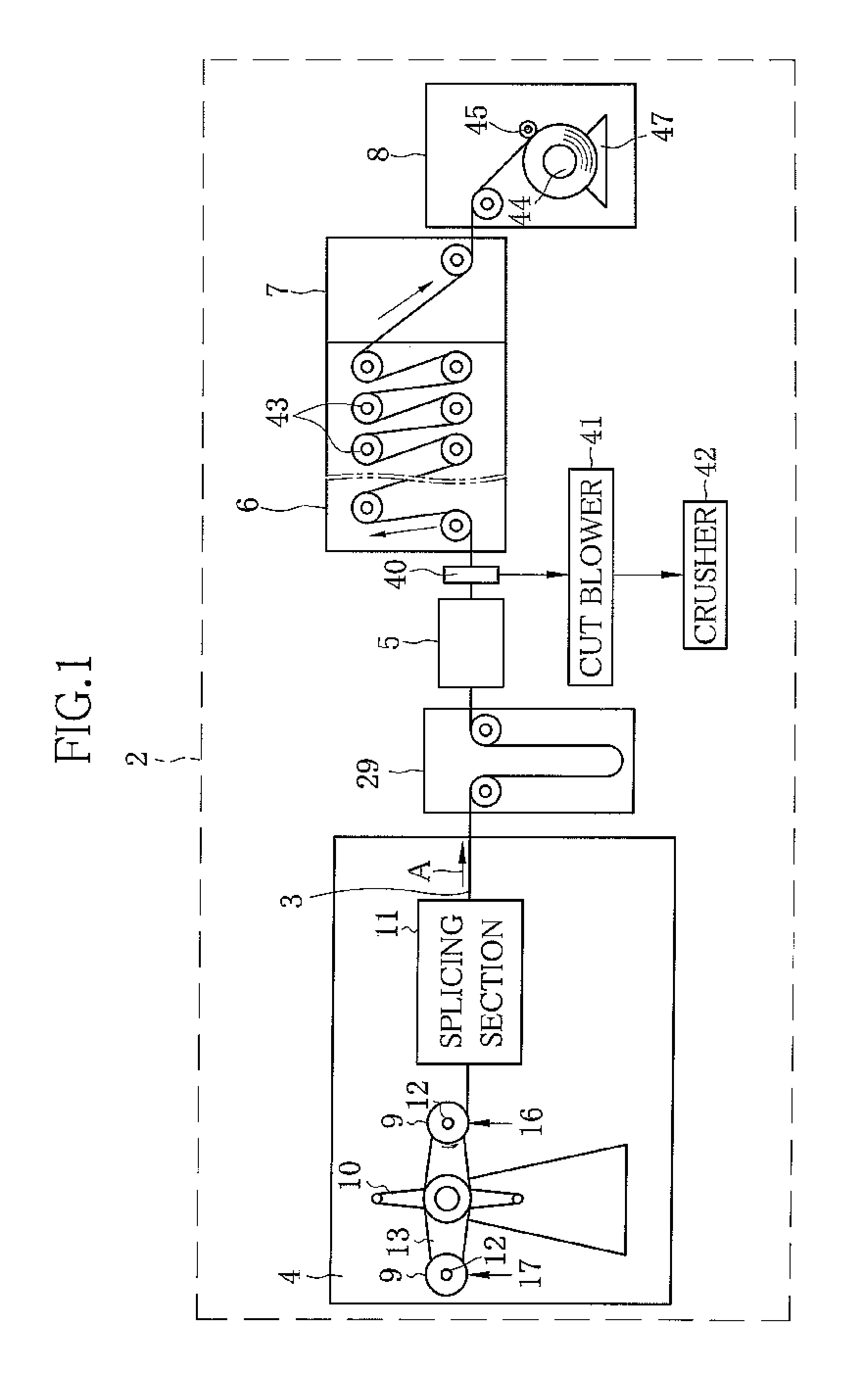
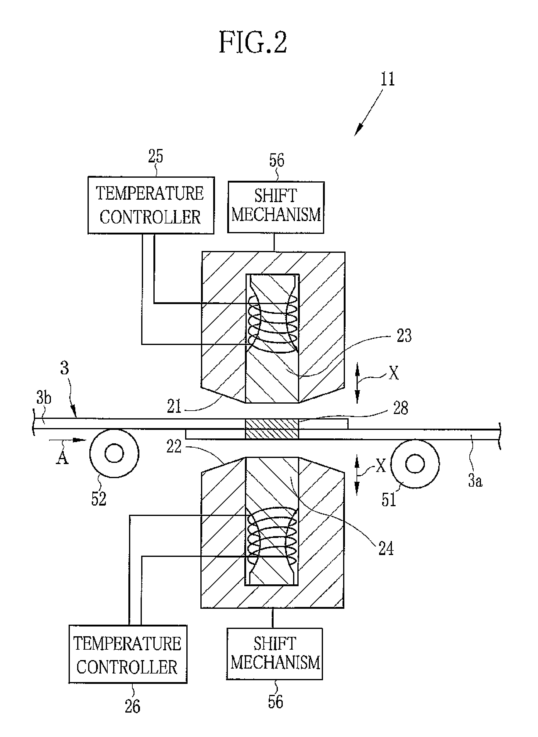
[0034]As shown in FIG. 1, an off-line stretching device 2 is used for stretching a TAC film 3 (hereinafter referred to as film 3), and includes a film supply chamber 4, a tenter section 5, a relaxation chamber 6, a cooling chamber 7, and a winding chamber 8 disposed in this order from a upstream side along a film transporting direction A. A film roll 9 produced in a solution casting apparatus is loaded in the film supply chamber 4. The film roll 9 is obtained by winding the film 3 around a core in a roll manner. The film 3 is fed from the film roll 9 loaded in the film supply chamber 4 to the tenter section 5. In the tenter section 5, the film 3 is continuously stretched in a film width direction while being heated. The stretched film 3 passes through the relaxation chamber 6 and the cooling chamber 7 to be cooled. The cooled film 3 is wound in the winding chamber 8. In the tenter section 5, the film 3 is stretched in the film width direction by 100.5% to 300%. In each of the film s...
embodiment 2
[0059]Although the preceding film 3a and the trailing film 3b are spliced to each other with use of the heat sealer 20 in the splicing section 11 in Embodiment 1, alternatively, as shown in FIG. 8, an ultrasonic splicer 50 can be used to splice the preceding film 3a and the trailing film 3b.
[0060]The ultrasonic splicer 50 mechanically vibrates the film 3, for example, 20,000 to 28,000 times / sec at the amplitude of 0.03 mm, to heat and weld the film 3. The ultrasonic splicer 50 includes two transducers 57, a horn 59, and a transmitter 53. A permanent magnet 54 is disposed between the transducers 57. A coil 55 is bridged over each of the transducers 57. The transmitter 53 causes the coil 55 to drive the transducers 57. The transducer 57 converts electrical vibration to mechanical vibration. The horn 59 amplifies the mechanical vibration caused by the transducer 57 to apply energy to the rear end of the preceding film 3a and the front end of the trailing film 3b (vibrate the rear end ...
embodiment 3
[0061]Although the preceding film 3a and the trailing film 3b are spliced to each other with use of the heat sealer 20 in the splicing section 11 in Embodiment 1, alternatively, as shown in FIG. 9, the splicing may be performed with use of acetone as one of the solvents contained in the dope used in forming the TAC film.
[0062]Acetone is applied to the spliced area 28 at the rear end of the preceding film 3a by spraying, and then the front end of the trailing film 3b is put on the rear end of the preceding film 3a. Thereafter, the rear end of the preceding film 3a and the front end of the trailing film 3b are spliced to each other by the acetone in a press-contact manner.
PUM
| Property | Measurement | Unit |
|---|---|---|
| decomposition temperature | aaaaa | aaaaa |
| melting point | aaaaa | aaaaa |
| rotation | aaaaa | aaaaa |
Abstract
Description
Claims
Application Information
 - R&D Engineer
- R&D Manager
- IP Professional
- Industry Leading Data Capabilities
- Powerful AI technology
- Patent DNA Extraction
Browse by: Latest US Patents, China's latest patents, Technical Efficacy Thesaurus, Application Domain, Technology Topic, Popular Technical Reports.
© 2024 PatSnap. All rights reserved.Legal|Privacy policy|Modern Slavery Act Transparency Statement|Sitemap|About US| Contact US: help@patsnap.com


