
Liquid crystal display device

a liquid crystal display and display panel technology, applied in non-linear optics, instruments, optics, etc., can solve the problems of liquid crystal display panel projecting from the display region of the face frame, unable to sufficiently reinforce the glass substrate using only polarizers, and possible problems, so as to achieve high-reliable liquid crystal display devices, reduce the total manufacturing cost, and ensure the effect of quality

Active Publication Date: 2012-03-20
PANASONIC INTELLECTUAL PROPERTY CORP OF AMERICA +1
View PDF7 Cites 18 Cited by
  • Summary
  • Abstract
  • Description
  • Claims
  • Application Information

AI Technical Summary

Benefits of technology

[0012]The present invention has been made to overcome the above-mentioned drawbacks, and it is an object of the present invention to provide a liquid crystal display device which can suppress lowering of image quality and can repair the liquid crystal display device while providing a bendable display screen.
[0026]According to the present invention, in the liquid crystal display device having the curved screen, the liquid crystal display panel is sandwiched between the face plate and the back plate, the upper polarizer is adhered to the face plate, and the lower polarizer is adhered to the back plate and hence, the highly reliable liquid crystal display device can be realized. Further, according to the present invention, when a trouble occurs in the liquid crystal display panel, the liquid crystal display panel is repaired by peeling off the polarizer and hence, the liquid crystal display panel can be reproduced thus lowering a total manufacturing cost.
[0027]Further, according to another aspect of the present invention, in the liquid crystal display device having the curved screen, the liquid crystal display panel is sandwiched between the face plate and the back plate, a portion of the upper polarizer is adhered to the color filter substrate, and a portion of the lower polarizer is adhered to the TFT substrate and hence, it is possible to realize the highly reliable liquid crystal display device. Further, according to the present invention, when a trouble occurs in the liquid crystal display panel, the liquid crystal display panel is repaired by peeling off the polarizer and hence, the liquid crystal display panel can be reproduced thus lowering a total manufacturing cost.

Problems solved by technology

However, it is difficult to sufficiently reinforce the glass substrate using only the polarizer.
That is, when a liquid crystal display panel disclosed in patent document 1 is arranged on a face frame, there arises a drawback that the liquid crystal display panel projects from a display region of the face frame.
However, this constitution requires an additional layer between polarizers and hence, there exists a possibility that the polarization direction is changed.
Accordingly, the liquid crystal display device has a drawback that when any trouble occurs in a manufacturing process, it is impossible to reproduce the liquid crystal display panel by repairing the liquid crystal display panel.

Method used


Image

  • Liquid crystal display device
  • Liquid crystal display device
  • Liquid crystal display device

Examples


embodiment 1

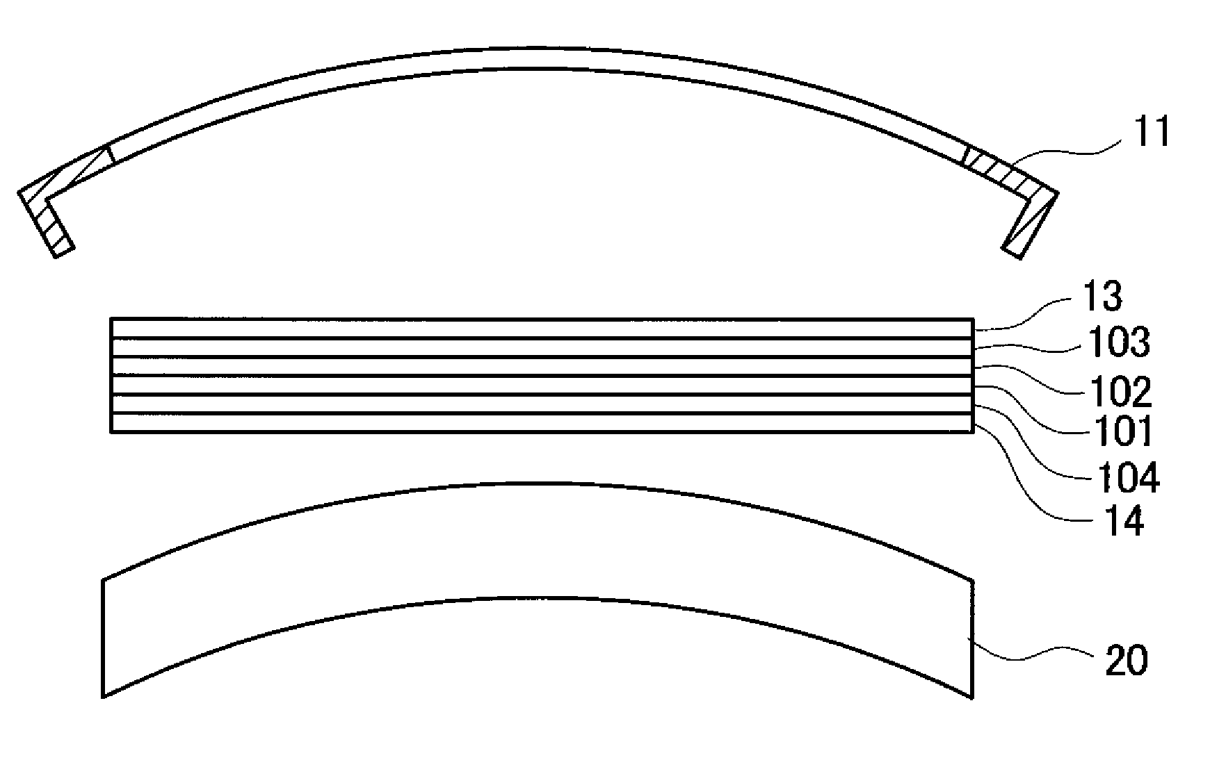
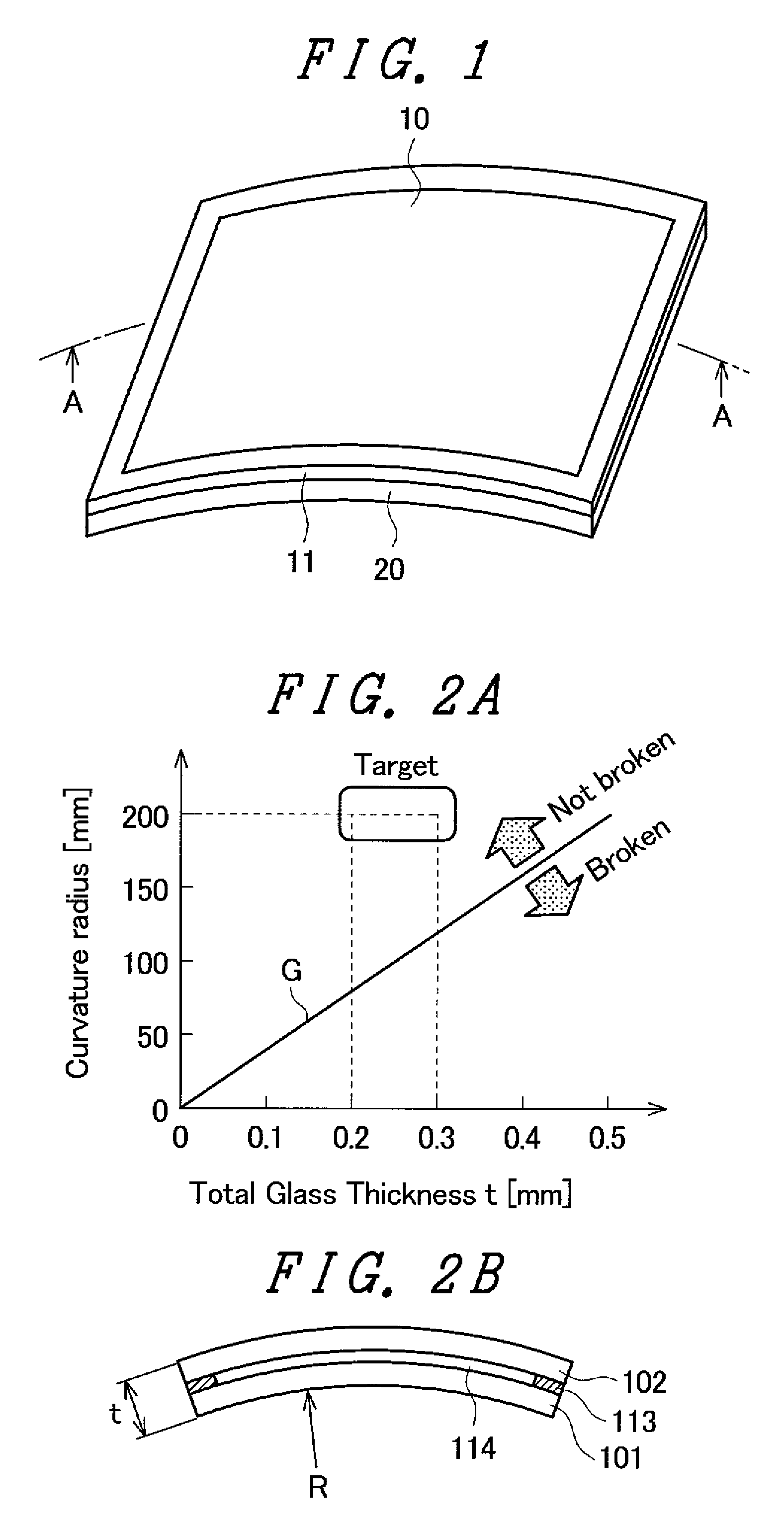
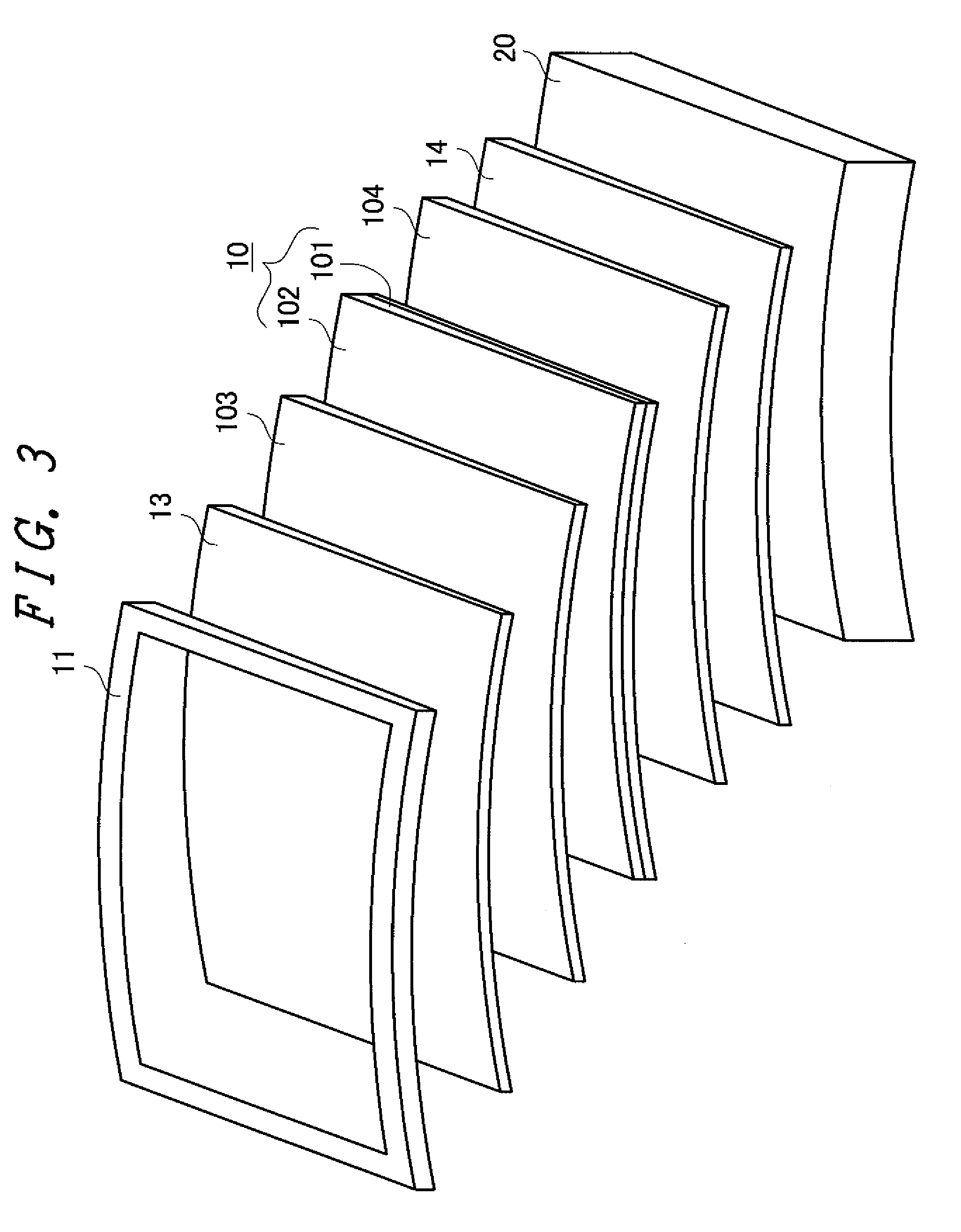
[0046]FIG. 1 is an appearance view of a liquid crystal display device of the embodiment 1. FIG. 1 shows a display having an outwardly projecting screen. Such a liquid crystal display device is used for an amusement application, that is, for a slot gaming machine or the like, for example. In FIG. 1, a liquid crystal display panel 10 is outwardly bent. According to this embodiment, in the outwardly-curved liquid crystal display panel 10, a substrate is made of glass. That is, to easily bend the liquid crystal display panel 10, the glass substrate is made thin. The liquid crystal display panel 10 is housed in the face frame 11 having a curved surface thus forming the liquid crystal display panel 10 having a curved screen. Although not shown in FIG. 1, the liquid crystal display panel 10 is covered with a transparent face plate 13 from above. That is, the face plate is arranged between the face frame 11 and the liquid crystal display panel 10.

[0047]In FIG. 1, the liquid crystal display ...

embodiment 2

[0071]In the case exemplified in conjunction with the embodiment 1, the polarizer is not adhered to the TFT substrate 101, the color filter substrate 102 and the like of the liquid crystal display panel 10 but is adhered to the face plate 13 and the back plate 14. However, in view of the accuracy of parts and other problems, there may be a case that the assembling accuracy of the liquid crystal display panel 10 and the polarizer cannot be acquired sufficiently. In such a case, when the polarizer is adhered to the glass substrate of the liquid crystal display panel 10 as in the case of the conventional technique, the liquid crystal display panel 10 cannot be reproduced when a defect occurs.

[0072]To cope with such a case, as shown in FIG. 11, by fixing a portion of the upper polarizer 103 or the lower polarizer 104 to the color filter substrate 102 or the TFT substrate 101 by way of an adhesive material or a tacky adhesive material 1031, the polarizer can be stably installed. In such ...

embodiment 3

[0074]In the embodiment 1 and the embodiment 2, the explanation is made with respect to a case that the display screen of the liquid crystal display device is outwardly projected. The present invention is also applicable to a case where the display screen is outwardly recessed (inwardly projected). By giving the outwardly recessed or concave shape to the display screen, it is possible to further make use of the characteristics of the liquid crystal display device.

[0075]FIG. 13 shows a viewing angle characteristic of the liquid crystal display device. One of drawbacks which the liquid crystal display device has in image quality is that brightness, chromaticity or the like is changed corresponding to a screen viewing angle. FIG. 13 shows the viewing angle characteristic of a usual TN-type liquid crystal display device. In FIG. 13, relative brightness is taken on an axis of ordinates and brightness when the screen is viewed in the direction perpendicular to the screen is set to 100%. I...


PUM

PropertyMeasurementUnit
thicknessaaaaaaaaaa
thicknessaaaaaaaaaa
thicknessaaaaaaaaaa

Abstract

In a liquid crystal display device having a liquid crystal display panel which includes a first substrate and a second substrate, a back plate is arranged on a first-substrate-side of the liquid crystal display panel, a first polarizer is arranged between the back plate and the first substrate, the first polarizer is adhered to the back plate, a face plate is arranged on a second-substrate-side of the liquid crystal display panel, a second polarizer is arranged between the face plate and the second substrate, and the second polarizer is adhered to the face plate.

Description

[0001]The present application claims priority from Japanese applications JP2008-159257 filed on Jun. 18, 2008, the content of which is hereby incorporated by reference into this application.BACKGROUND OF THE INVENTION[0002]1. Field of the Invention[0003]The present invention relates to a liquid crystal display device, and more particularly to a liquid crystal display device having a curved display screen.[0004]2. Background Art[0005]Thanks to several favorable characteristics of a liquid crystal display device such as the reduction of thickness of the display device and the reduction of weight of the display device, a demand for a liquid crystal display device has been spreading to various applications ranging from a computer display, a mobile phone display or the like to a television receiver set. Since the liquid crystal display device can reduce a thickness of a liquid crystal display panel thereof, recently, the liquid crystal display device has been also used as a display devic...

Claims


Application Information

Patent Timeline
Patent Type & Authority Patents(United States)
IPC IPC(8): G02F1/1333
CPCG02F1/133305G02F2001/13332G02F2001/133331G02F2202/09G02F1/13332G02F1/133331
Inventor NISHIZAWA, SHIGEKI
Owner PANASONIC INTELLECTUAL PROPERTY CORP OF AMERICA
Learn More