
Wide-band planar antenna

a planar antenna and wideband technology, applied in the direction of antennas, antenna details, antenna earthings, etc., can solve the problems of limiting the miniaturization of electronic devices, unable to meet wimax requirements, and the low frequency band mode's bandwidth of about 200 mhz, so as to reduce the required materials and reduce the production cost

Active Publication Date: 2012-03-13
WISTRON NEWEB
View PDF8 Cites 21 Cited by
  • Summary
  • Abstract
  • Description
  • Claims
  • Application Information

AI Technical Summary

Benefits of technology

The present invention provides a wide-band planar antenna that reduces required materials and production costs. It has three different frequency bands through direct and coupling feed-in methods to accommodate different frequencies. The antenna prevents reflective waves in a specific bandwidth to enhance the power of electromagnetic waves and save more electrical power compared with a general antenna. The antenna includes a substrate, three radiators, a ground, and a signal source. The substrate has two surfaces and the radiators are disposed on the surfaces or different surfaces of the substrate. The ground connects to the third radiator and includes a first and second ground parts. The signal source feeds a high frequency signal to excite the radiators and generate the frequency band modes.

Problems solved by technology

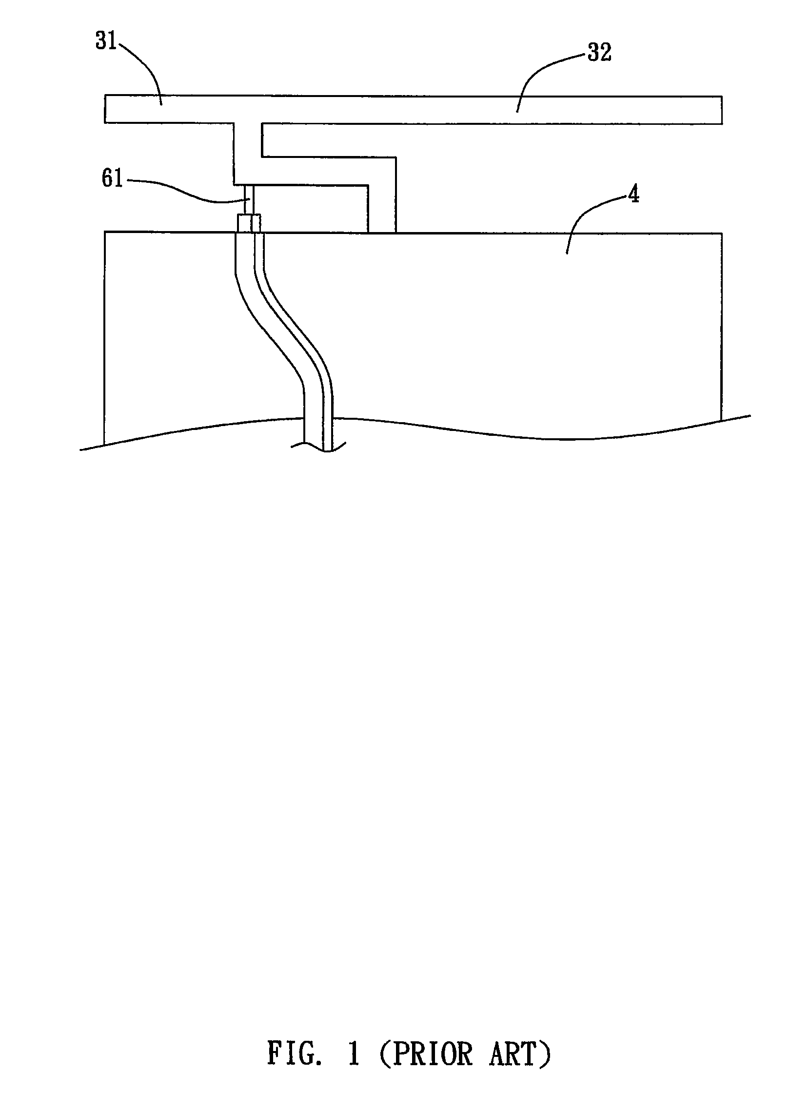
Because the antenna is fed with signals in a direct-feed-in manner, the bandwidth of the low frequency band mode is about 200 MHz, which cannot satisfy WiMAX requirement.
Furthermore, in order to meet the operating frequency of the low frequency band mode, the length of the second radiator 32 cannot be further reduced resulting in the restriction of miniaturization of the electronic devices.

Method used


Image

  • Wide-band planar antenna
  • Wide-band planar antenna
  • Wide-band planar antenna

Examples


Embodiment Construction

[0031]It is an object of the invention to provide a wide-band planar antenna and a manufacture process thereof. By a smaller and thinner design, the production cost can be drastically decreased. By designing the radiator for a specific bandwidth, reflective waves can be reduced to increase the power of electromagnetic waves so as to save more electrical power. In an embodiment, a wide-band planar antenna has a wireless communication function applicable to various electronic devices. The electronic devices preferably include laptops, desktop computers, motherboards, mobile phones, personal digital assistants, global positioning systems, electronic game devices, and so on. The wireless signal transmitted / received by the wide-band planar antenna can be applied to wireless local area network (WLAN), WiMAX, and other wireless communication protocols or standards.

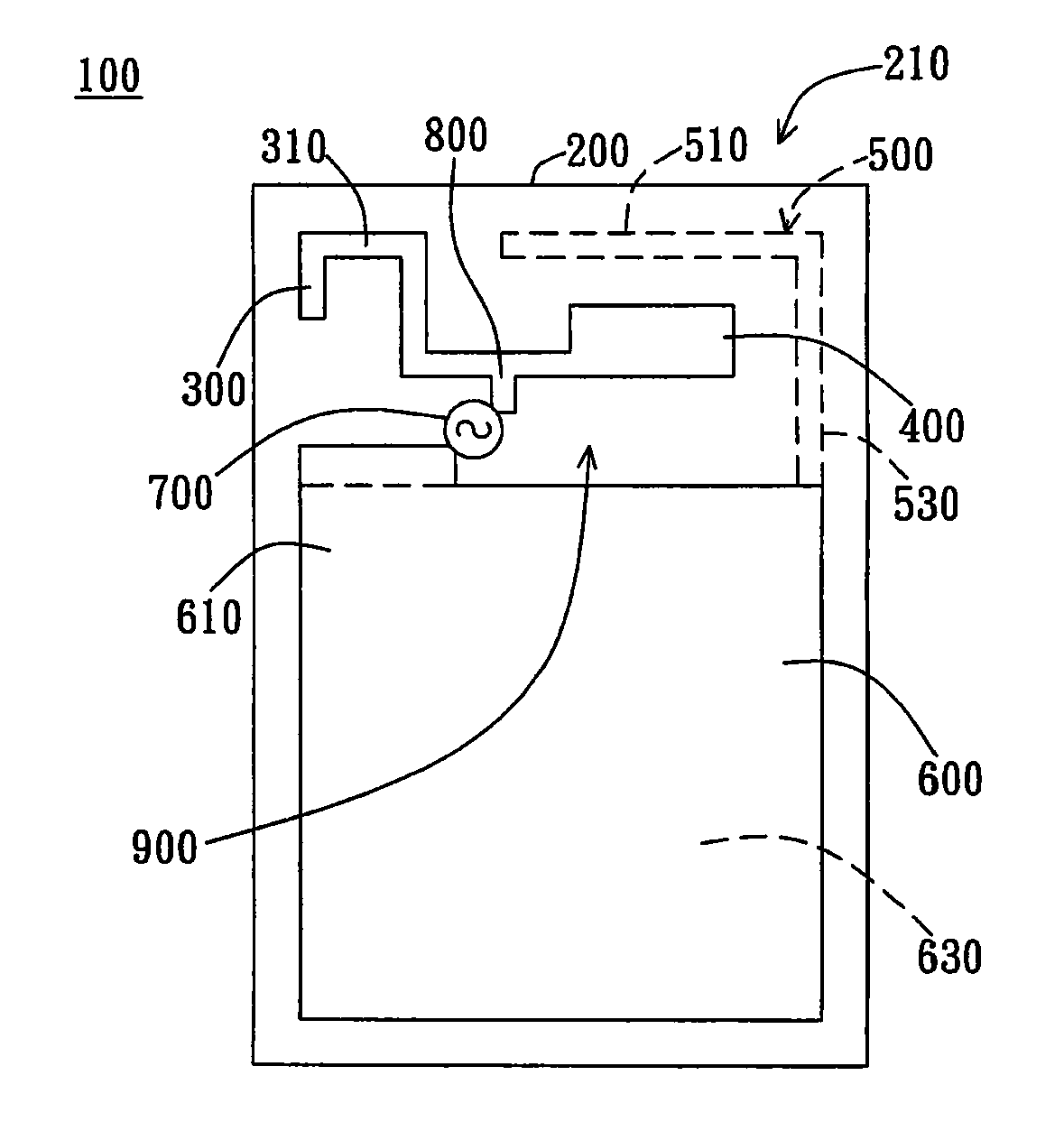
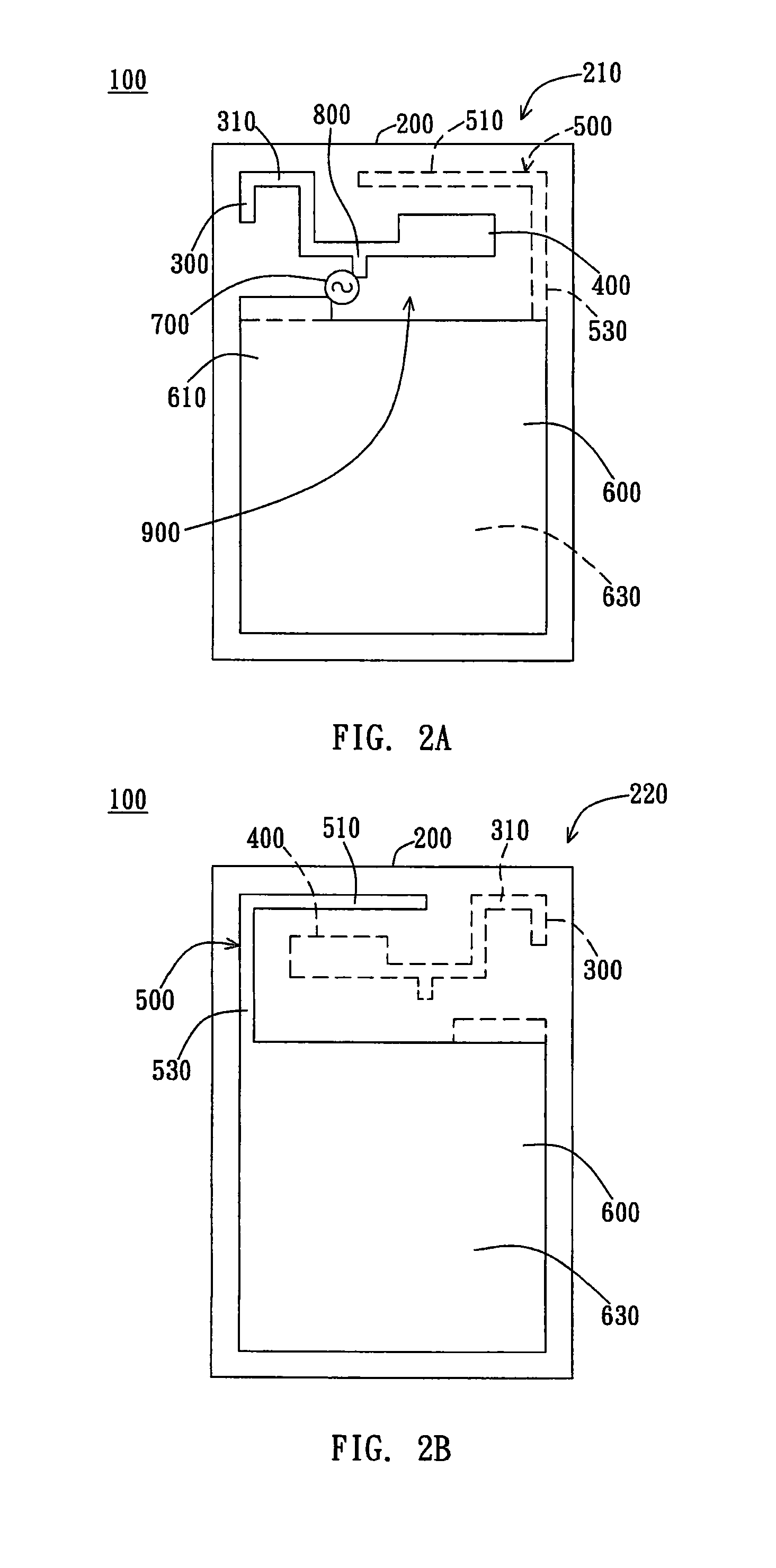
[0032]FIG. 2A and FIG. 2B show schematic views of the wide-band antenna of the invention. With reference to FIG. 2A and FIG. 2B...


PUM


Abstract

The invention relates to a wide-band planar antenna. The wide-band planar antenna includes a substrate, a first radiator, a second radiator, a third radiator, a ground, and a signal source. The first radiator, the second radiator, and the third radiator are designed in a manner that the antenna of the invention can be applied to WiMAX communication devices. Besides, the wide-band planar antenna of the invention is more efficient than a general wide-band antenna and saves a significant amount of electrical power, and therefore, the antenna is particularly suitable for portable communicational devices.

Description

[0001]This application claims the priority based on a Taiwanese patent application No. 097141365, filed on Oct. 28, 2008, the disclosure of which is incorporated herein by reference in its entirety.BACKGROUND OF THE INVENTION[0002]1. Field of the Invention[0003]The present invention relates to a wide-band antenna; more particularly, the present invention relates to a wide-band planar antenna for wireless network communications.[0004]2. Description of the Prior Art[0005]As the physical Internet becomes more and more popular, people pay much attention to a wireless, long-distance, and wide-band network in place of the physical Internet to increase the popularity in wideband communications. Thus, more advanced wireless communication network technologies and standards continuously emerge. For example, Wi-Fi wireless network standard is previously defined in IEEE 802.11 by Institute of Electrical and Electronics Engineers (IEEE); Worldwide Interoperability for Microwave Access (WiMAX) is...

Claims


Application Information

Patent Timeline
Patent Type & Authority Patents(United States)
IPC IPC(8): H01Q1/48H01Q5/371H01Q5/378
CPCH01Q1/243H01Q5/378H01Q5/371H01Q9/42
Inventor WANG, CHIH-MINGTSENG, SHANG-CHING
Owner WISTRON NEWEB
Learn More