
System and method for evaluating petroleum reservoir using forward modeling

a petroleum reservoir and forward modeling technology, applied in stochastic cad, instruments, borehole/well accessories, etc., can solve the problems of large computer cpu power consumption, inability to use recorded raw measurement response on its own, and high computational cost of inversion method, so as to achieve less cpu time. the effect of demanding

Inactive Publication Date: 2012-03-06
SCHLUMBERGER TECH CORP
View PDF3 Cites 19 Cited by
  • Summary
  • Abstract
  • Description
  • Claims
  • Application Information

AI Technical Summary

Benefits of technology

[0011]Other steps can be added to this process to further refine the models. In this process, most steps of simulation involved are forward calculation, thus the process is less CPU time demanding compared with the conventional EM inversion approach. The results of the simulation are actually useful reservoir properties, defined as original reservoir properties later in this patent, such as porosity, permeability, salinity, saturation. A reservoir engineer can use such properties to predict reservoir behavior.

Problems solved by technology

The recorded raw measurement response, however, are not useful on their own.
First of all, the inversion method is very computational intensive and time consuming.
The forward calculation as well as the calculation of the modification values usually consume a large amount of the computer CPU power.
Secondly, results of the inversion method could be misleading.
In fact, most geophysical inversion processes are massively underdetermined.
Thus the answer derived from the inversion process may be the answer that best matches the optimization mathematical criteria, but it does not necessarily reflect the physically correct answer.
In addition, generally inversion schemes do not provide any information about the range of possible answers that may all be supported almost equally well by the measured data.
Thirdly, and most importantly, data obtained through the inversion method may not be useful for the reservoir engineer.
However, such a resistivity model is not useful in and of itself.
Therefore resistivity is not a reservoir property that a reservoir engineer can use directly to predict reservoir performance or plan production management.
What makes the problem even worse is that resistivity is a function of several directly useful reservoir properties including porosity, water saturation, water salinity, etc.
A reservoir engineer does not have any tool to guide him to obtain these useful reservoir properties from a resistivity value.
The inversion scheme or inversion results do not provide any guidance on the important step of obtaining directly useful reservoir properties.

Method used


Image

  • System and method for evaluating petroleum reservoir using forward modeling
  • System and method for evaluating petroleum reservoir using forward modeling
  • System and method for evaluating petroleum reservoir using forward modeling

Examples


Embodiment Construction

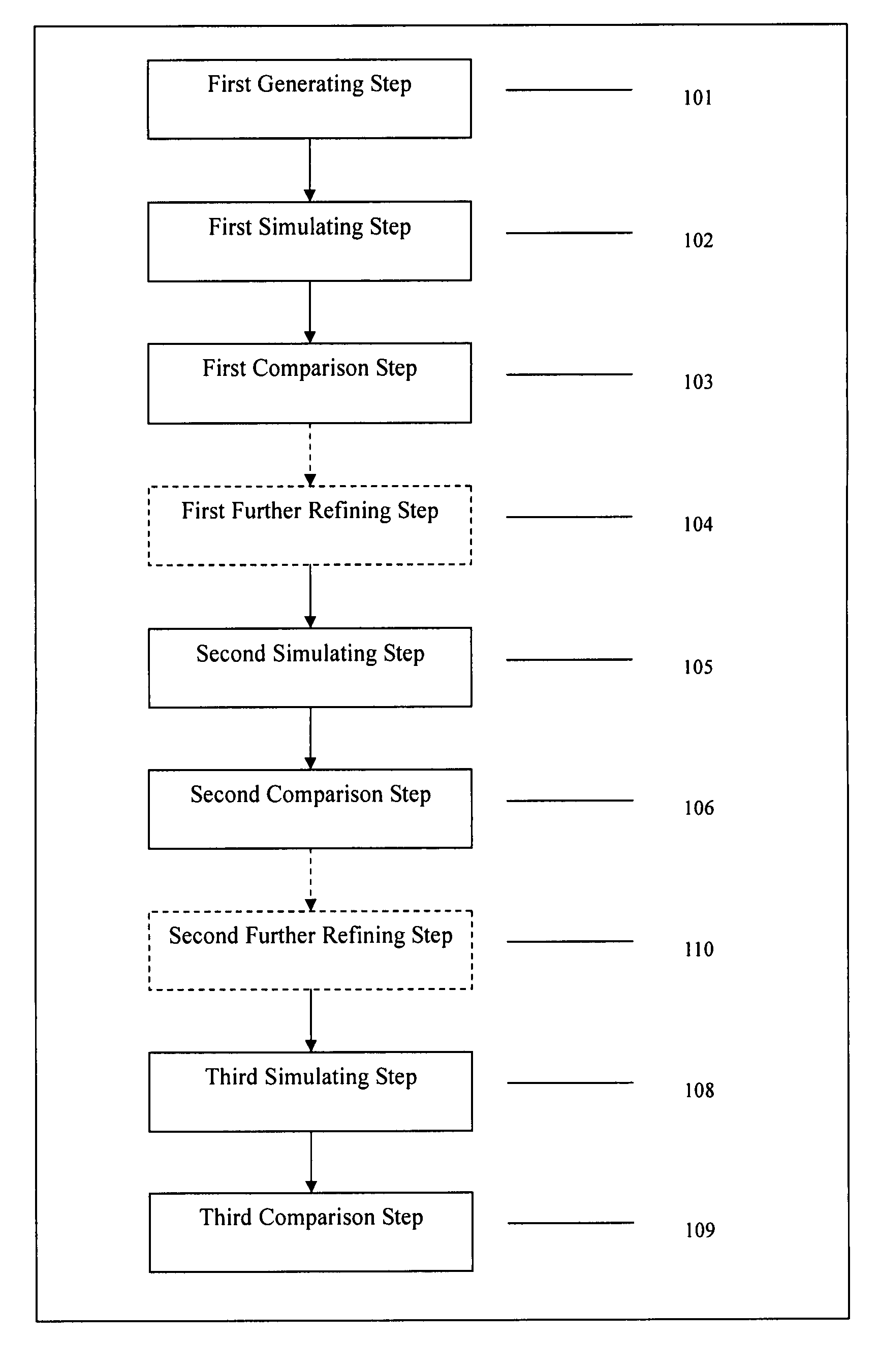
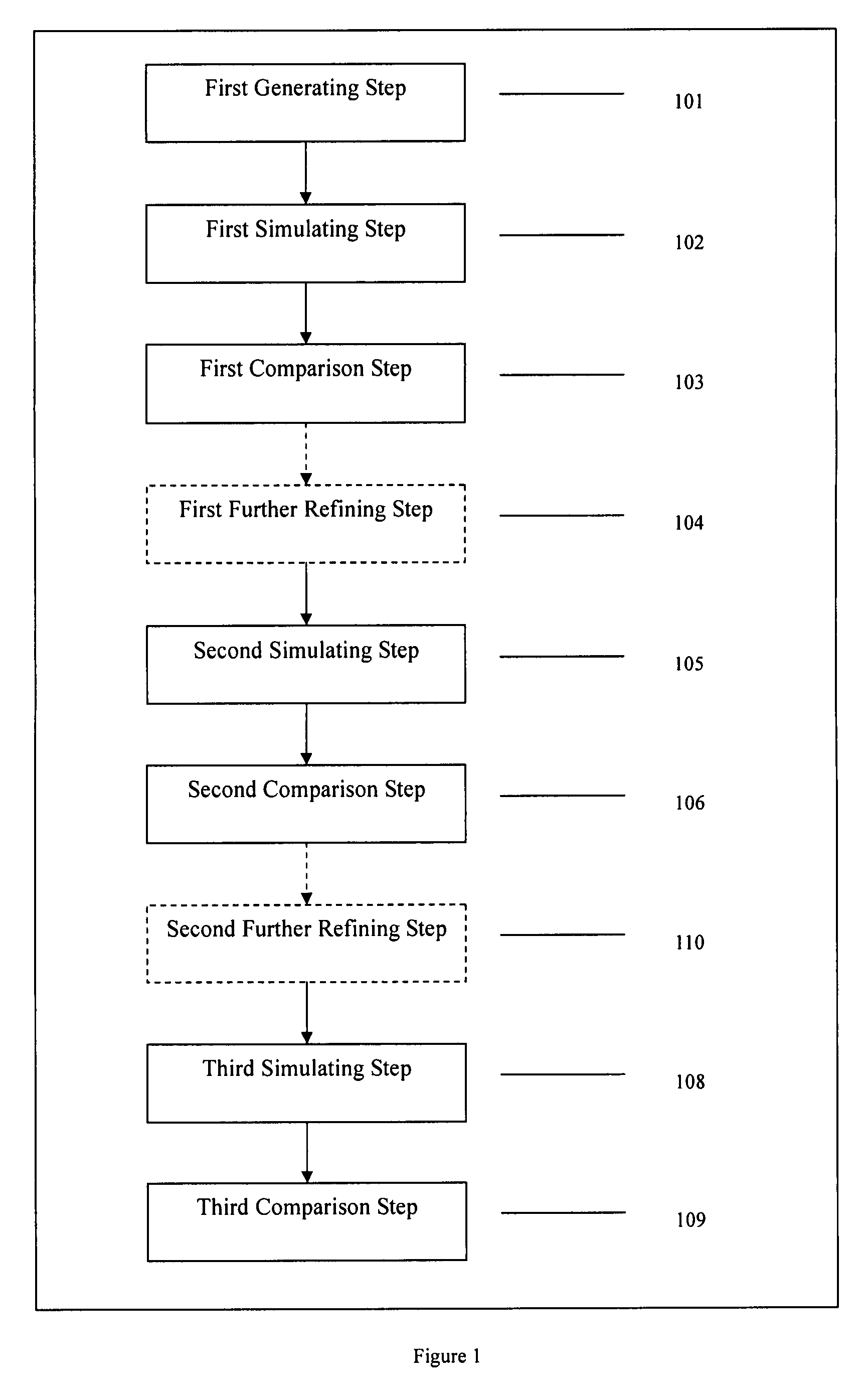
[0018]FIG. 1 is a schematic flow chart of the steps of the system and method of this invention. According to the method and system of this invention, one needs to generate a first group of subsurface reservoir models. This step is shown as step 101 in FIG. 1. We define this step as the first generating step. The first group of subsurface reservoir models should be established using original reservoir properties. In this invention, an original reservoir property is defined as the property of the reservoir that a reservoir engineer can use in a conventional finite difference reservoir simulation program for calculating reservoir performance. Examples of original reservoir properties include porosity, permeability, oil saturation, gas saturation, water saturation and water salinity, pore structure, pore wettability, etc. Resistivity is not considered an original reservoir property within the definition of this invention.

[0019]Original reservoir properties for a reservoir differ from lo...


PUM


Abstract

This invention relates to petroleum reservoir characterization. It uses a novel system and method to generate a system of reservoir models, and then use a series of simulation techniques to simulate the models. The models are refined through each simulation and comparison step by comparing the results of the simulation with the known data from the reservoir. The invention can be applied to different reservoirs which have different known properties. Simulation techniques such as EM test forward calculation, stochastic reservoir modeling, streamline forward calculation are all candidates of simulation methods disclosed in the invention.

Description

FIELD OF THE INVENTION[0001]The disclosure relates in general to petroleum reservoir, and more particularly to system and method for evaluating petroleum reservoir.BACKGROUND OF THE INVENTION[0002]Cross well electromagnetic tomography (“EM”) has been available as a reservoir evaluation technology for approximately fifteen years. To obtain cross well electromagnetic tomography data, one needs to locate a receiver in one well and a transmitter in another well. The receiver would stay at one depth while the transmitter travels up and down the well while transmitting electromagnetic signals. The receiver receives the signal and transmits the signal up to the surface, where the received signal is recorded against the depth of both the transmitter and the receiver. The receiver would then be moved to another depth and the transmitter again travels up and down the well transmitting signals to be received by the receiver. At the end of an EM log, the recorder would have recorded a complete ...

Claims


Application Information

Patent Timeline
Patent Type & Authority Patents(United States)
IPC IPC(8): G06G7/48
CPCE21B49/00G06F17/5009G06F2217/10G06F2217/16G06F30/20G06F2111/08G06F2111/10
Inventor NEVILLE, THOMAS J.
Owner SCHLUMBERGER TECH CORP
Learn More