
Tool bucket organizer

a tool and bucket technology, applied in the field of tool holders, can solve the problems of wasting time looking, wasting time, and wasting time, and achieve the effect of saving time and searching time without fear of loss or damag

Inactive Publication Date: 2012-03-06
MILLER KIRK W
View PDF17 Cites 16 Cited by
  • Summary
  • Abstract
  • Description
  • Claims
  • Application Information

AI Technical Summary

Benefits of technology

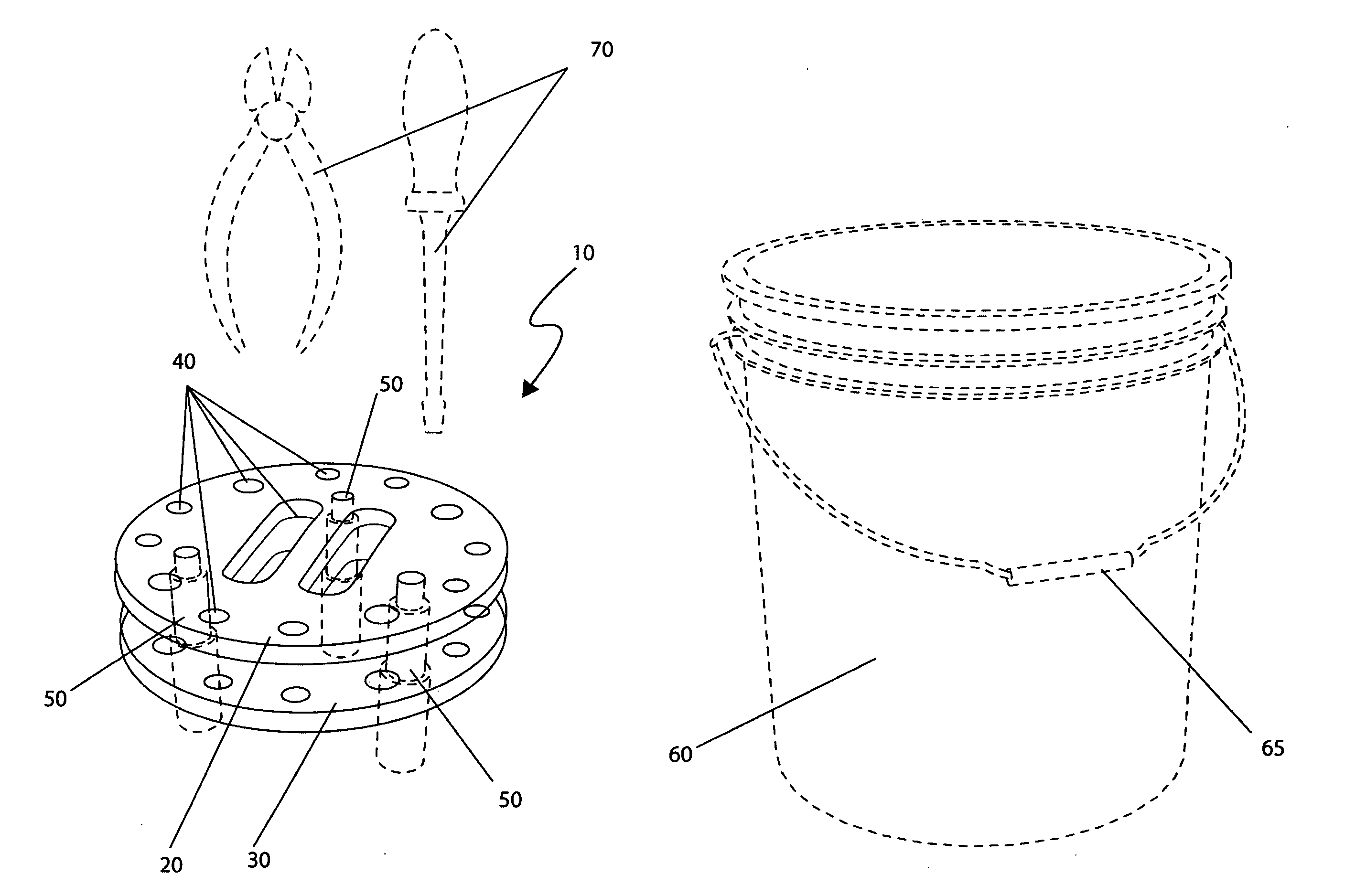
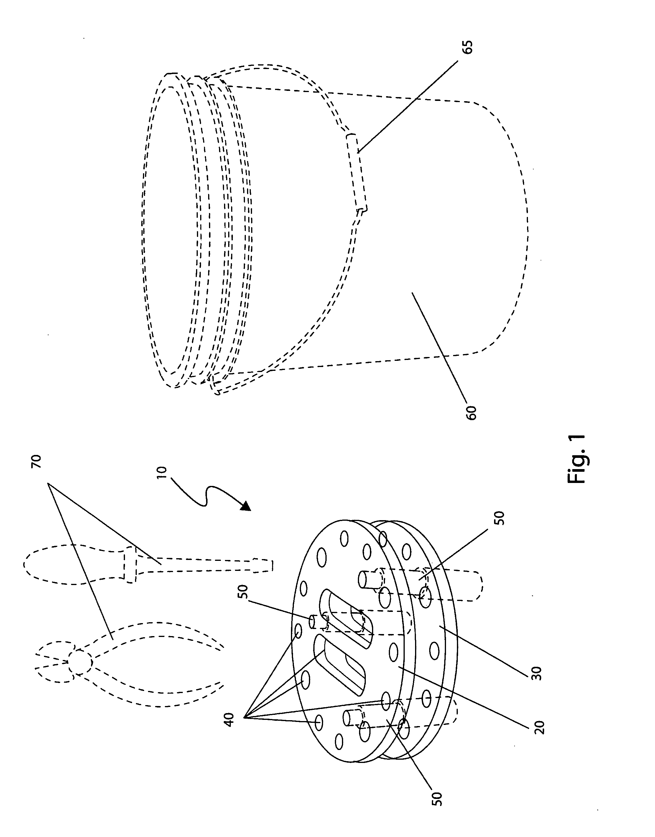
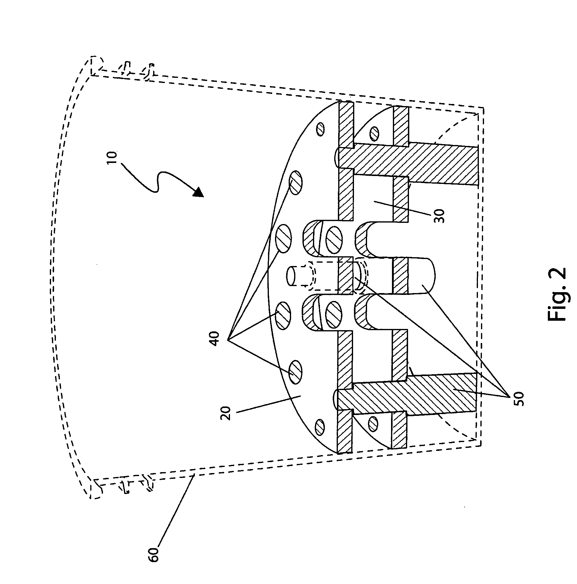
[0013]To achieve the above objectives, it is an object of the present invention to provide a tool bucket organizer which provides a means for storing and organizing small hand tools. The invention is slidingly inserted into a bucket and provides a rigid organizing structure within the bucket for tools to be held.
[0021]Yet still another object of the bucket organizer is to provide the middle portion which provides the distance between the upper and lower disks and the resting means for the upper disk to set comprising a radial horizontal surface.
[0025]Yet still another object of the bucket organizer is to provide a method of utilizing the device which allows professionals and do-it-yourself handymen the ability to store and transport hand tools without fear of loss or damage while at the same time saving time in looking for the tool when needed.

Problems solved by technology

In many cases the buckets cannot be reused for their initial purpose, especially when used for food packaging, and therefore have historically been thrown away and sent to the landfill leading to thousands of buckets a day discarded.
Another has been to carry multiple tool boxes, bags, or material containers which can be cumbersome and inconvenient.
One (1) disadvantage they pose however is that the tools typically end up in a tangled mess in the middle of the container or hang loosely from the sides.
The canvas tool holders force the user to pull open and peer inside of each pocket, all of which takes time and caused aggravation while performing a task.
However, none of these designs are similar to the present device.
While these devices fulfill their respective, particular objectives, each of these references suffers from one or more of the aforementioned disadvantages.

Method used


Image

  • Tool bucket organizer
  • Tool bucket organizer
  • Tool bucket organizer

Examples


Embodiment Construction

[0032]The best mode for carrying out the invention is presented in terms of its preferred embodiment, herein depicted within the FIGS. 1 and 3. However, the invention is not limited to the described embodiment and a person skilled in the art will appreciate that many other embodiments of the invention are possible without deviating from the basic concept of the invention, and that any such work around will also fall under scope of this invention. It is envisioned that other styles and configurations of the present invention can be easily incorporated into the teachings of the present invention, and only one particular configuration shall be shown and described for purposes of clarity and disclosure and not by way of limitation of scope.

[0033]The terms “a” and “an” herein do not denote a limitation of quantity, but rather denote the presence of at least one of the referenced items.

[0034]The present invention describes a device and method for a tool bucket organizer (herein described ...


PUM


Abstract

An insert for containers designed to store and organize small hand tools comprising two (2) discs, each of a slightly smaller diameter than the interior diameter of the bucket is herein disclosed. Each disc is provided with multiple holes and slots to hold various types of hand tools. The discs are separated a few inches from each other and the lower insert is held off the bottom of the bucket by a set of legs. The insert is designed to hold hand tools such as screwdrivers, pliers, wrenches, hammers, utility knifes and the like. The configuration of the discs allows each tool to stand upright and not fall over, enabling a user to quickly find a desired hand tool.

Description

RELATED APPLICATIONS[0001]The present invention was first described in a notarized Official Record of Invention on Jun. 3, 2008, that is on file at the offices of Montgomery Patent and Design, LLC, the entire disclosures of which are incorporated herein by reference.FIELD OF THE INVENTION[0002]The present invention relates generally to a tool holder and, more particularly, to said holder which provides a removable tool holding and organizing means for use with plastic buckets.BACKGROUND OF THE INVENTION[0003]The plastic five-gallon bucket, while initially intended as packaging for building materials, food, and the like from a manufacturer or distributer, have become a very popular and utilitarian tool for many people. In many cases the buckets cannot be reused for their initial purpose, especially when used for food packaging, and therefore have historically been thrown away and sent to the landfill leading to thousands of buckets a day discarded. Thus, in this age of growing enviro...

Claims


Application Information

Patent Timeline
Patent Type & Authority Patents(United States)
IPC IPC(8): B65D25/32
CPCB25H3/04
Inventor MILLER, KIRK W.
Owner MILLER KIRK W
Learn More