Axial flux machine arrangement

a technology of axial flux machine and axial axis, which is applied in the direction of mechanical energy handling, magnetic circuit rotating parts, shape/form/construction, etc., can solve the problems of rotor not being able to rotate, loss of rigid structure in which a bearing can be mounted to support rotors, and inoperable motors, so as to increase the overall torque output of the machine

Active Publication Date: 2018-11-08
YASA LIMITED
View PDF0 Cites 7 Cited by
  • Summary
  • Abstract
  • Description
  • Claims
  • Application Information

AI Technical Summary

Benefits of technology

The patent text describes a very compact machine design that can be integrated into a hybrid power train or a single unit power train with an integrated clutch. The machine includes a stator and rotor with a clutch mechanism housed within the confines of the machine. A clutch plate bearer is used to secure the rotor to the stator, and a machine housing is used to enclose the rotor, providing a rigid structure. In some configurations, the machine includes a second rotor with permanent magnets and an axial gap between the stator and second rotor, which increases the overall torque output of the machine. The method also includes arranging a clutch plate bearing and attaching a machine housing to the stator housing to further protect the rotor from the external environment. The technical effects of this patent claim a more efficient and compact machine design with improved torque output and protection from environmental factors.

Problems solved by technology

As can be appreciated, dispensing with the stator yoke provides a substantial saving in weight and iron losses, but one drawback is loss of rigid structure in which a bearing can be mounted to support rotors.
In the limit there is possibility of interference of rotor on stator and hence rotor not being able to rotate and a motor being inoperable or catastrophic motor failure if interference occurs during use.
This arrangement provides excellent repeatability of said air gap in motor production, but the teaching of WO2010 / 092402 lacks flexibility particularly when interfacing with a clutch which is sometimes a requirement for these motors when they are used in hybrid machines.
In a similar fashion Thomas U.S. Pat. No. 6,585,066 has integrated a wet multi-plate clutch within a radial flux motor, but there are significant shortcomings from taking this approach including; a large diameter of motor, risk of electrical shorts in end-windings of the stator due to debris from the clutch, difficulty of rotor to stator assembly and increased axial length due to stator end-windings.
The end-windings are also prone to catching debris which can lead to electrical shorts and debris in this instance is made by the clutch during normal use.
The challenge of radial flux machine assembly is compounded when integrated around a clutch and having bearings that are outboard of the stator, rotor and clutch assembly.

Method used


Image

  • Axial flux machine arrangement
  • Axial flux machine arrangement
  • Axial flux machine arrangement

Examples


Embodiment Construction

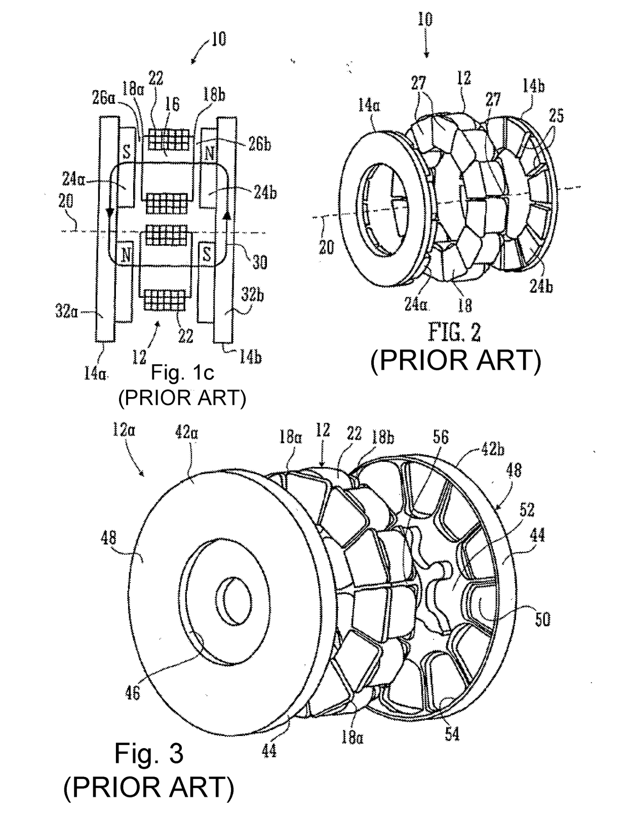
[0045]Referring first to FIGS. 1c, 2 and 3, which are taken from our PCT application WO2012 / 022974, FIG. 1c shows a schematic illustration of a yokeless and segmented armature machine 10.

[0046]The machine 10 comprises a stator 12 and two rotors 14a,b. The stator 12 is a collection of separate stator bars 16 spaced circumferentially about a rotation axis 20 of the rotors 14a,b. Each bar 16 has its own axis (not shown) which is preferably, but not essentially, disposed parallel to the rotation axis 20. Each end of each stator bar is provided with a shoe 18a,b which serves a physical purpose of confining a coil stack 22, which stack 22 is preferably of square / rectangular section insulated wire so that a high fill factor can be achieved. The coils 22 are connected to an electrical circuit (not shown) that, in the case of a motor, energizes the coils so that the poles of the resultant magnetic fields generated by the current flowing in the coils is opposite in adjacent stator coils 22.

[0...


PUM


Abstract

An axial flux machine is provided with an integrated clutch assembly, which is housed within the bore of an annulus-shaped stator of the machine. First and second rotors, located either side of the stator are attached to the clutch basket of the clutch assembly, and rotate in unison relative to the stator. A machine housing is provided between the stator and an engagement face of the clutch basket, seated on bearings between the clutch basket and machine housing, to provide a rigid structure.

Description

FIELD OF THE INVENTION[0001]The present invention relates to an axial flux machine, in particular an axial flux machine comprising a clutch arrangement.BACKGROUND OF THE INVENTION[0002]In the present invention, we are concerned with axial flux permanent magnet machines. Broadly speaking these have disc- or ring-shaped rotor and stator structures arranged about an axis. Typically the stator comprises a set of coils each parallel to the axis and the rotor bears a set of permanent magnets and is mounted on a bearing so that it can rotate about the axis driven by fields from the stator coils. FIG. 1a shows the general configuration of an axial flux machine of the present invention with a pair of rotors R1, R2 to either side of a stator S—although a simple structure of the present invention could omit one of the rotors. As can be seen there is an air gap G between a rotor and a stator and in an axial flux machine the direction of flux through the air gap is substantially axial.[0003]Ther...

Claims


Application Information

Patent Timeline
Patent Type & Authority Applications(United States)
IPC IPC(8): H02K7/108H02K1/18H02K1/20H02K1/27H02K7/00H02K15/16H02K16/02H02K21/24
CPCH02K7/108H02K1/182H02K1/20H02K1/2793H02K7/003H02K15/165H02K16/02H02K21/24H02K2205/09H02K7/085H02K15/03H02K1/2798H02K15/16H02K7/006
Inventor WOOLMER, TIM
Owner YASA LIMITED
Why Eureka
Try Eureka