
Sealing apparatus and gas turbine having same

a sealing apparatus and gas turbine technology, applied in the direction of machines/engines, liquid fuel engines, light and heating apparatus, etc., can solve the problems of deterioration of performance, difficult sealing to apply to a low no/sub>(premix) combustor, and the wire brush b>102/b>may collapse or wear

Active Publication Date: 2012-02-28
MITSUBISHI POWER LTD
View PDF8 Cites 12 Cited by
  • Summary
  • Abstract
  • Description
  • Claims
  • Application Information

AI Technical Summary

Benefits of technology

The present invention provides a sealing apparatus with high sealing performance, low cost, and good assembly characteristics. The sealing apparatus comprises a minimum number of seal pieces connected in a longitudinal direction, which can flex and seal between adjacent members. The seal pieces can be connected by a flexible sheet or tied together with wires. A sealing metal foil can be used between the connecting surfaces of the seal pieces. The invention also includes a gas turbine equipped with the sealing apparatus, which can achieve low NOx emissions and full performance of a low NOx combustor.

Problems solved by technology

However, the seal shown in FIG. 5 has posed the problem that the deformation of the wire brush 102b at the time of combustor assembly and after operation of the gas turbine is marked, arousing a concern about deterioration of performance, so that the seal is difficult to apply to a low NOx (premix) combustor.
That is, the wire brush 102b may collapse or wear when the clearance changes at the time of combustor assembly, during operational vibrations, or at start or stoppage of the gas turbine.
There has also been the problem that the cost for repair of the combustor increases because of replacement work necessitated by deformation after operation.
However, increases in processing man-hours and the number of the components have presented the problem of cost increases.
The sealing apparatus shown in FIG. 7 has involved the problems that an increase in the number of the components results in a cost increase, and the sealing body 107 is integrally formed, and lacks flexibility, leading to poor assembly characteristics within a narrow space.

Method used


Image

  • Sealing apparatus and gas turbine having same
  • Sealing apparatus and gas turbine having same
  • Sealing apparatus and gas turbine having same

Examples


embodiment 1

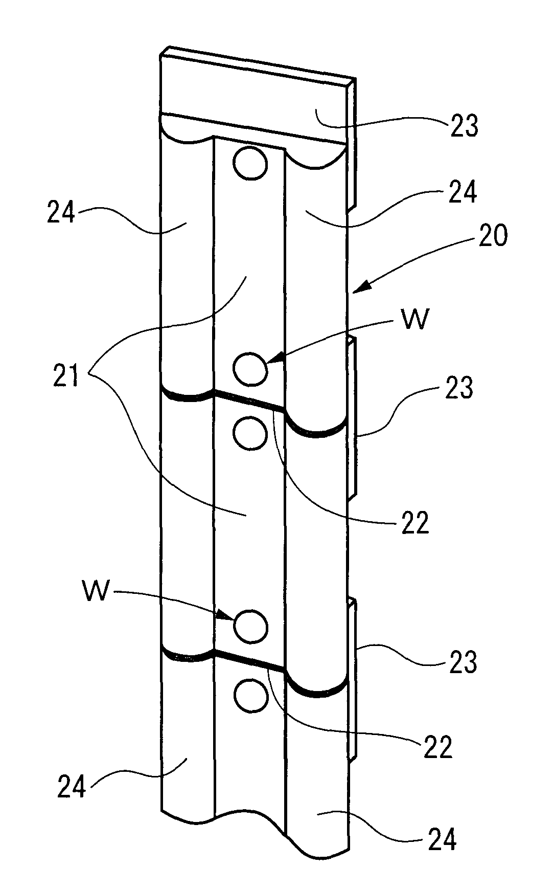
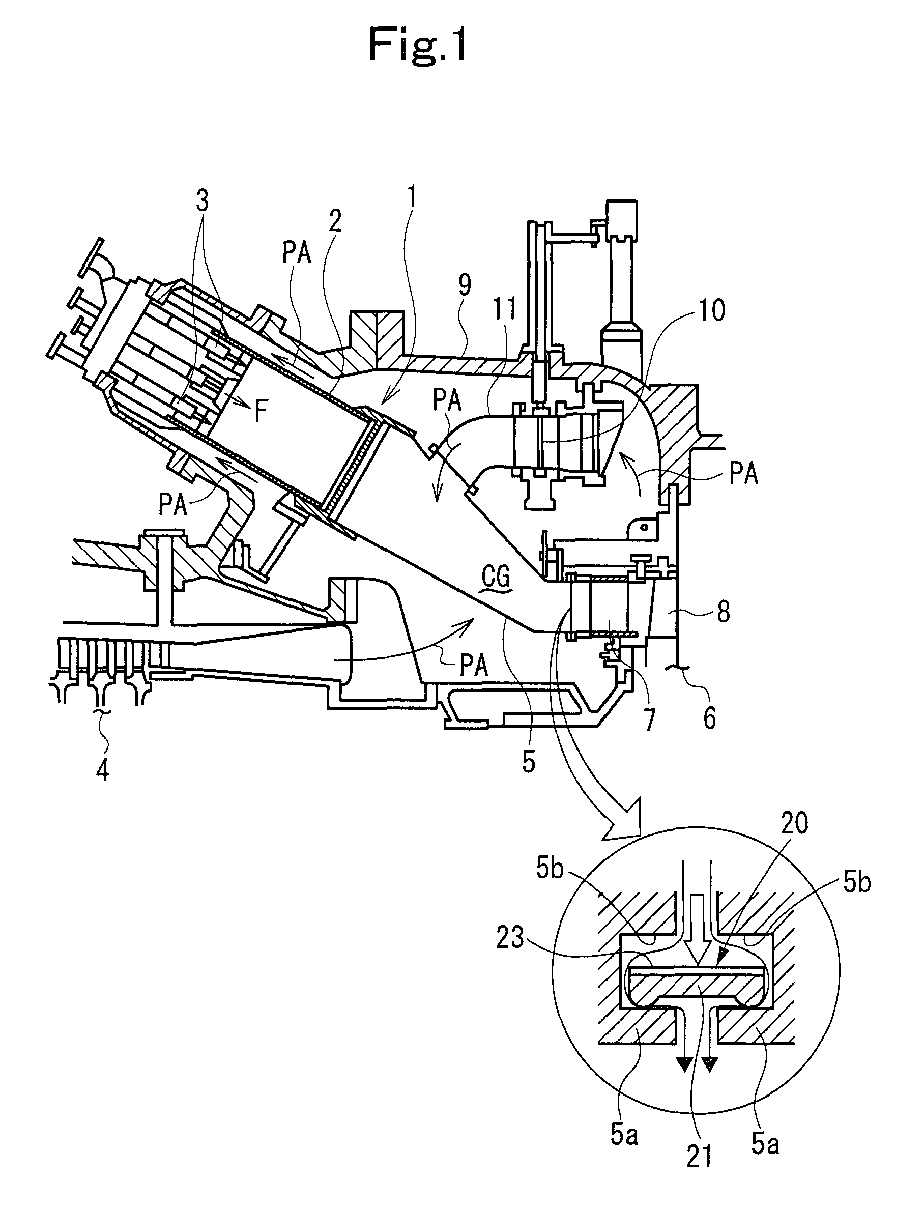
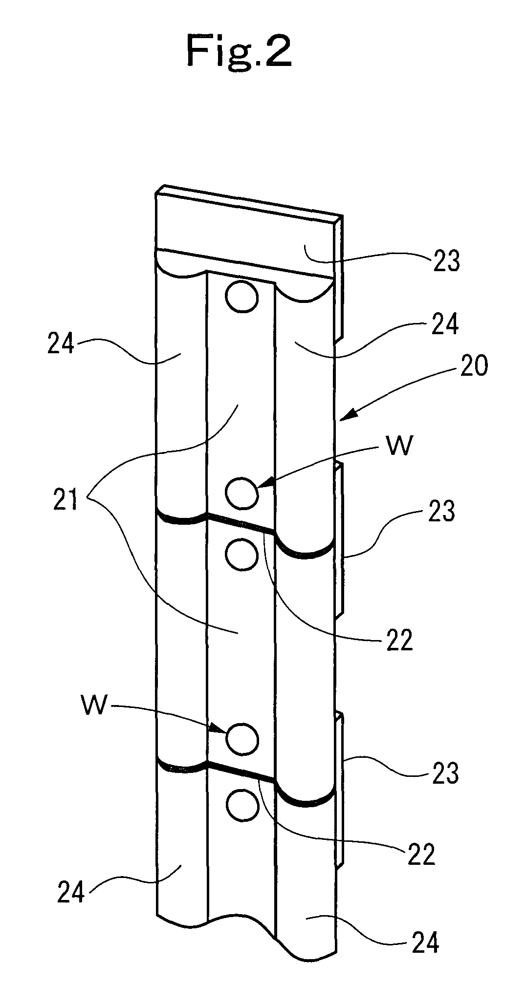
[0030]FIG. 1 is a schematic configurational drawing of essential parts of a gas turbine showing Embodiment 1 of the present invention. FIG. 2 is a perspective view of essential parts of a sealing apparatus in the gas turbine.

[0031]As shown in FIG. 1, a gas turbine has a plurality of (e.g., 16) combustors 1 of a low NOx (premix) type arranged around a main shaft (rotating shaft; not shown). In each combustor 1, a fuel F injected from fuel nozzles 3 provided adjacent to a combustor inner tube 2, and compressed air PA ejected from an air compressor (will hereinafter be referred to simply as a compressor) 4 and introduced to the upstream side of the combustor inner tube 2 are mixed. Then, the mixture is burned in a combustion region on the downstream side of the combustor inner tube 2 or the upstream side of a combustor transition pipe 5, and is introduced into a turbine 6 as a high temperature, high pressure combustion gas CG. In the turbine 6, this combustion gas CG is sequentially pa...

embodiment 2

[0040]FIG. 3 is a plan view of a sealing apparatus showing Embodiment 2 of the present invention.

[0041]This is an embodiment in which the seal pieces 21 in Embodiment 1 are arranged symmetrically on both surfaces of the sheet 23. The sealing apparatus according to this embodiment can be used as a sealing apparatus between the components when the flowing direction of leaking air is reversed in the seal groove 5b.

embodiment 3

[0042]FIG. 4 is a configurational drawing of a sealing apparatus showing Embodiment 3 of the present invention.

[0043]This is an embodiment in which seal pieces 21A as in Embodiment 1, formed by press-working to have sealing ridges 24A of a semi-annular cross section, are laminated in a superposed manner by spot welding W, and a plurality of the resulting laminates are tied (connected) together in the longitudinal direction by two wires 25. That is, each wire 25 is inserted into the circular hole formed by the two sealing ridges 24A opposing each other.

[0044]According to the present embodiment, like Embodiment 1, the sealing apparatus 20 can be realized which has a small number of the components, whose production is easy, and which is wear resistant. Thus, it has high sealing performance, and can achieve cost reduction. Since the core material is the wire 25, moreover, moderate flexibility can be imparted, and assembly characteristics can also be enhanced.


PUM


Abstract

It is an object of the present invention to provide a sealing apparatus having high sealing performance, entailing a low cost, and satisfactory in assembly characteristics. The sealing apparatus is a differential pressure-responsive sealing apparatus which is inserted between seal grooves formed in the side surfaces of outlet flange portions of adjacent combustor transition pipes to seal clearance between the side surfaces, comprising: a minimum required number of seal pieces connected in the longitudinal direction for imparting flexibility, the seal piece comprising a heat resistant, wear resistant material, and having a pair of sealing ridges each having an arcuate surface contacting the wall surface of each seal groove.

Description

BACKGROUND OF THE INVENTION[0001]1. Field of the Invention[0002]This invention relates to a sealing apparatus, and a gas turbine having this apparatus. More particularly, the invention relates to a sealing apparatus for sealing clearance between assembly components which changes owing to external force or thermal expansion or the like, for example, a sealing apparatus suitable as a seal between gas turbine combustors at their outlets.[0003]2. Description of the Related Art[0004]Generally, a gas turbine has an air compressor (may hereinafter be referred to as “compressor”), a combustor, and a turbine as main constituents. The combustor is disposed between the compressor and the turbine connected together directly by a rotating shaft. Air to serve as a working fluid is taken into the compressor in accordance with the rotation of the rotating shaft, and compressed there. The compressed air is introduced into the combustor, and burned with a fuel. The resulting combustion gas at a high ...

Claims


Application Information

Patent Timeline
Patent Type & Authority Patents(United States)
IPC IPC(8): F16J15/02
CPCF01D9/023F16J15/0887F05D2240/57
Inventor FUJIMOTO, KIYOSHIKISHIDA, HIROAKIAOYAMA, KUNIAKI
Owner MITSUBISHI POWER LTD
Learn More