
Multi-chips with an optical interconnection unit

a multi-chip, optical interconnection technology, applied in the direction of solid-state devices, instruments, material analysis, etc., can solve the problems of difficult manufacturing of compact chips, difficult to realize compact multi-chip packages, and signal delay

Active Publication Date: 2012-02-21
SAMSUNG ELECTRONICS CO LTD
View PDF21 Cites 66 Cited by
  • Summary
  • Abstract
  • Description
  • Claims
  • Application Information

AI Technical Summary

Benefits of technology

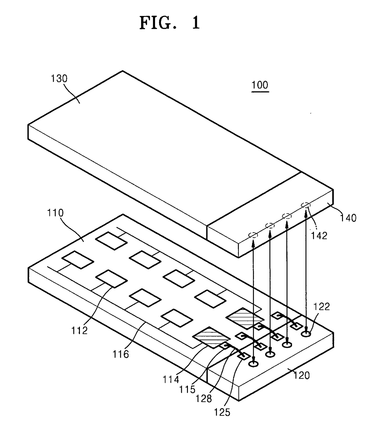
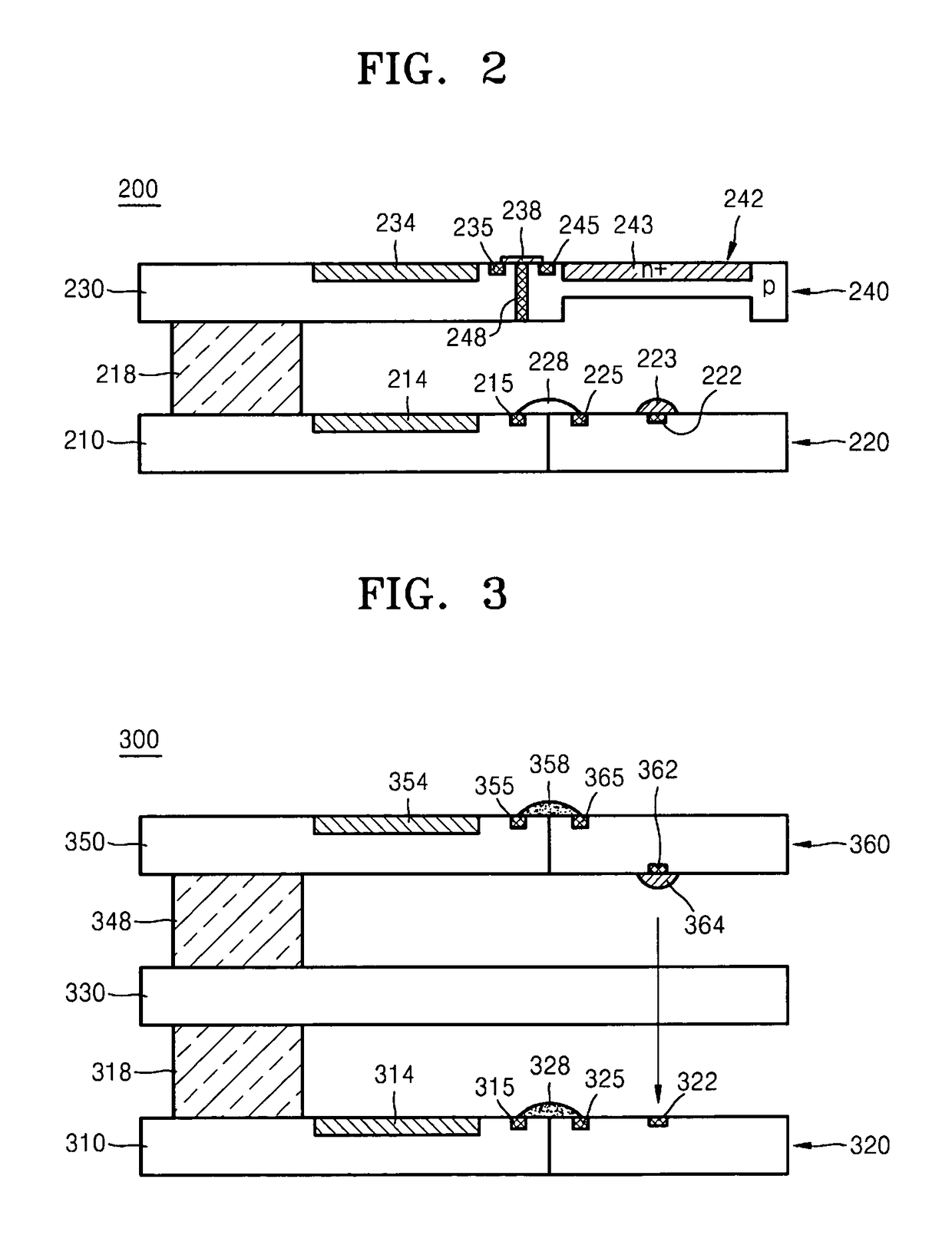
This patent relates to multi-chips with optical interconnection units and methods of manufacturing them. The technical effect of this patent is to provide a more efficient and compact way of connecting multiple silicon chips through optical interconnections, which can be used in various applications such as high-speed data transmission and optical inter-chip communication. The optical device arrays on the sides of the silicon chips can be arranged and connected using wiring, and a focusing lens can be used to improve the optical connection. The light emitting devices and light receiving devices can be formed of different materials and can be positioned close to each other to facilitate the optical connection.

Problems solved by technology

In the wire bonding method, as the length of the wire increases, a signal delay may occur if an ultra high speed signal is transmitted.
Because the wire bonding method requires bonding pads, the bonding pad area increases as the stacking number of the silicon chips increases, making it difficult to manufacture a compact chip.
Because the thicknesses of the light emitting device and the light receiving device are approximately between a few tens of μm to 200 μm, an inter layer distance between the facing chips increases, making it difficult to realize a compact multi-chip package.

Method used


Image

  • Multi-chips with an optical interconnection unit
  • Multi-chips with an optical interconnection unit

Examples


Embodiment Construction

[0026]Various example embodiments will now be described more fully with reference to the accompanying drawings in which some example embodiments are shown. In the drawings, the thicknesses of layers and regions may be exaggerated for clarity.

[0027]Detailed illustrative embodiments are disclosed herein. However, specific structural and functional details disclosed herein are merely representative for purposes of describing example embodiments. This invention may, however, may be embodied in many alternate forms and should not be construed as limited to only example embodiments set forth herein.

[0028]Accordingly, while example embodiments are capable of various modifications and alternative forms, embodiments thereof are shown by way of example in the drawings and will herein be described in detail. It should be understood, however, that there is no intent to limit example embodiments to the particular forms disclosed, but on the contrary, example embodiments are to cover all modifica...


PUM


Abstract

A multi-chip having an optical interconnection unit is provided. The multi-chip having an optical interconnection unit includes a plurality of silicon chips sequentially stacked, a plurality of optical device arrays on a side of each of the plurality of the silicon chips such that the optical device arrays correspond to each other and a wiring electrically connecting the silicon chip and the optical device array attached to a side of the silicon chip, wherein the corresponding optical device arrays forms an optical connection unit by transmitting and receiving an optical signal between the corresponding optical device arrays in different layers. Each of the optical device arrays includes at least one of a light emitting device and a light receiving device.

Description

PRIORITY STATEMENT[0001]This application claims the benefit of priority under 35 U.S.C. §119 from Korean Patent Application No. 10-2007-0112313, filed on Nov. 5, 2007, in the Korean Intellectual Property Office, the disclosure of which is incorporated herein in its entirety by reference.BACKGROUND[0002]1. Field[0003]Example embodiments relate to multi-chips having an optical interconnection unit and methods of manufacturing the same. Other example embodiments relate to multi-chips having an optical interconnection unit on a side of the multi-chip and methods of manufacturing the same.[0004]2. Description of the Related Art[0005]In a multi-chip structure in which silicon chips are stacked, a connection method (e.g., a wire bonding method or a through silicon via hole connection method) may be used for an electrical connection between the silicon chips.[0006]In the wire bonding method, as the length of the wire increases, a signal delay may occur if an ultra high speed signal is trans...

Claims


Application Information

Patent Timeline
Patent Type & Authority Patents(United States)
IPC IPC(8): H01L27/15H01L33/00H01L29/16H01L31/12
CPCG02B6/43H01L2224/49175H01L2224/48137H01L2224/05554H01L2924/00
Inventor CHO, SOO-HAENGHA, KYOUNG-HORYU, HAN-YOULSUH, SUNG-DONGKIM, SEONG-GUMIN, BOK-KI
Owner SAMSUNG ELECTRONICS CO LTD
Learn More