Electrodynamic transducer and use thereof in loudspeakers and geophones

a transducer and electrodynamic technology, applied in the direction of transducer details, electric transducers, electrical apparatus, etc., can solve the problems of reducing the output magnetic field, reducing the output power, and unable to take advantage of the power increas

Active Publication Date: 2012-02-07
GILLES MILOT +1
View PDF13 Cites 14 Cited by
  • Summary
  • Abstract
  • Description
  • Claims
  • Application Information

AI Technical Summary

Benefits of technology

[0010]The present invention proposes to take advantage of the whole power of the magnets by avoiding the use of ferromagnetic or magnetic materials to loopback, by physical guidance, the magnetic field created by one or more magnets of a transducer.
[0122]The advantages resulting from the invention, besides obtaining a more strong field in which the moving coil is immersed, are a reduction of the part number of the transducer, a more important displacement possibility for the coil-bearing mandrel and / or a dimension reduction given the absence of physical loopback of the magnetic field by a ferromagnetic or magnetic part between the internal and external volumes. The dynamic behavior of the transducer is improved by the fact that the inductance of the coil generally remains constant whatever the position it takes because of the absence of ferromagnetic material in the motor or, in case of presence of such materials, of an insignificant effect because of the low quantity thereof relative to traditional solutions which use a loopback of the magnetic field with a ferromagnetic part extending between the internal and external spaces of the motor.
[0128]Then, a motor having only an internal construction presents poor characteristics relative to a motor having an external construction, wherein the latter is however not optimal because of the field lines structure. Yet, combining an external construction with an internal construction improves the quality of the field in which the coil is immersed, thanks to a reciprocal guiding effect of the field lines between and within these two constructions. It has even been shown that, by combining an external construction with an internal construction, it is possible to obtain at the coil a field which is approximately twice higher than the one obtained with only an external construction. Such a gain is obtained with a quantity of magnetic material far lesser than what should be used to obtain the same result with only one construction, either external or internal.
[0129]Therefore, besides the improvement of the magnetic field structure in which the coil is immersed, of the strength thereof, weight and cost savings can be obtained.
[0130]Finally, the implementation of at least one ferromagnetic part in the given conditions allow, on one part, the increasing of the global field to which the coil is subjected by decreasing of the leakages outside the motor, and on the other part, a better control of the shape of the magnetic field plateau ends along the height direction of the motor. Further, these parts are also useful in the case in which ferrofluidic seals are implemented. Indeed, these ones are preferentially placed in areas having a great variation (gradient) of the magnetic field and a high field.

Problems solved by technology

Now, the power of magnets increases in a progressive manner and ferromagnetic materials can be saturated by too strong magnetic fields, whereupon it becomes impossible to take advantage of that power increase.
However, losses occur in ferromagnetic material and the outgoing magnetic field is no longer homogeneous and decreases as the distance from the magnet increases.
Further, the presence of such materials changes the inductance of the coil and involves changes in this inductance when the coil moves within the air gap.
Finally, so-called “Foucault currents” induced in those ferromagnetic parts can still disturb the transducer operation.

Method used


Image

  • Electrodynamic transducer and use thereof in loudspeakers and geophones
  • Electrodynamic transducer and use thereof in loudspeakers and geophones
  • Electrodynamic transducer and use thereof in loudspeakers and geophones

Examples


Embodiment Construction

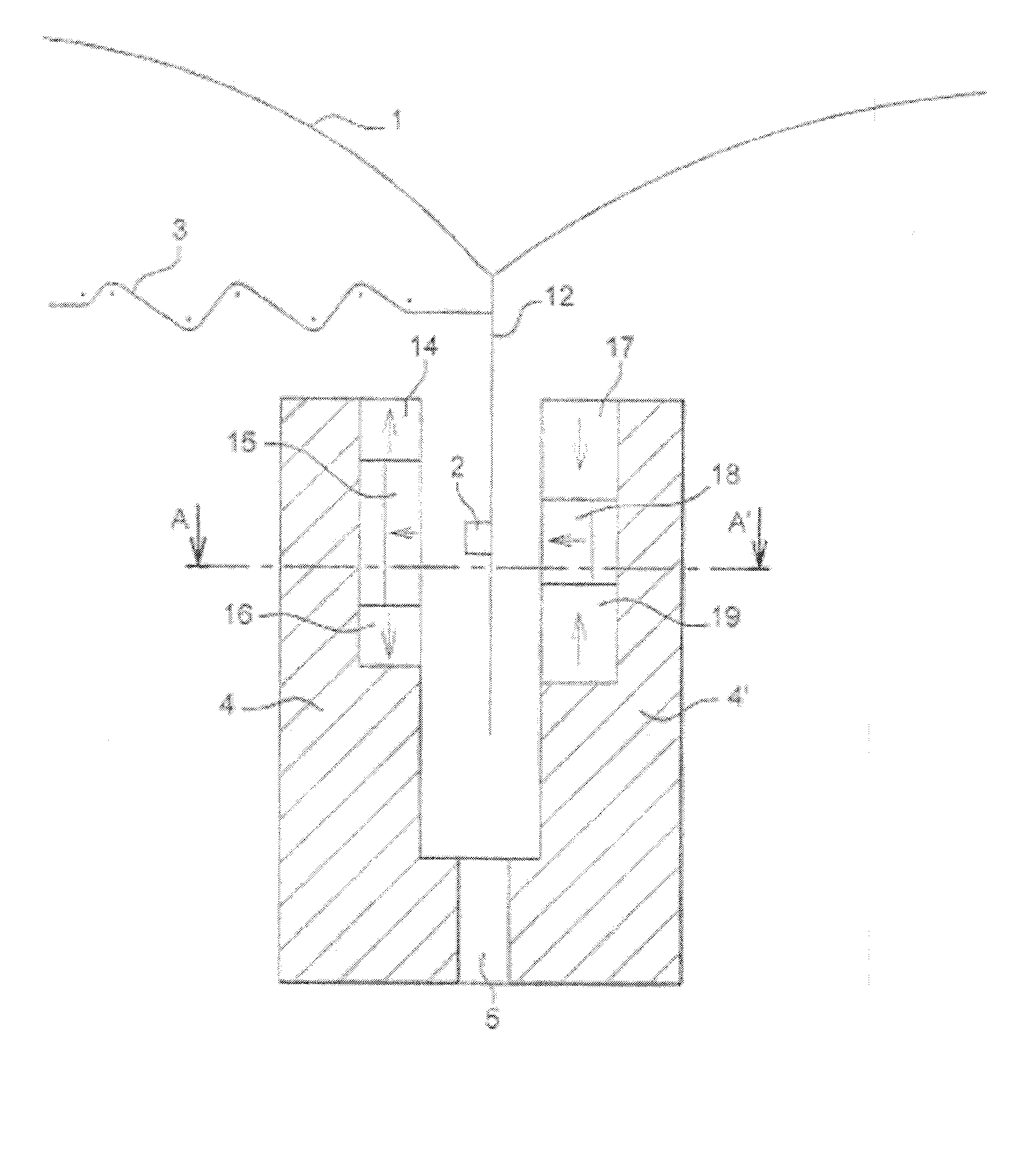
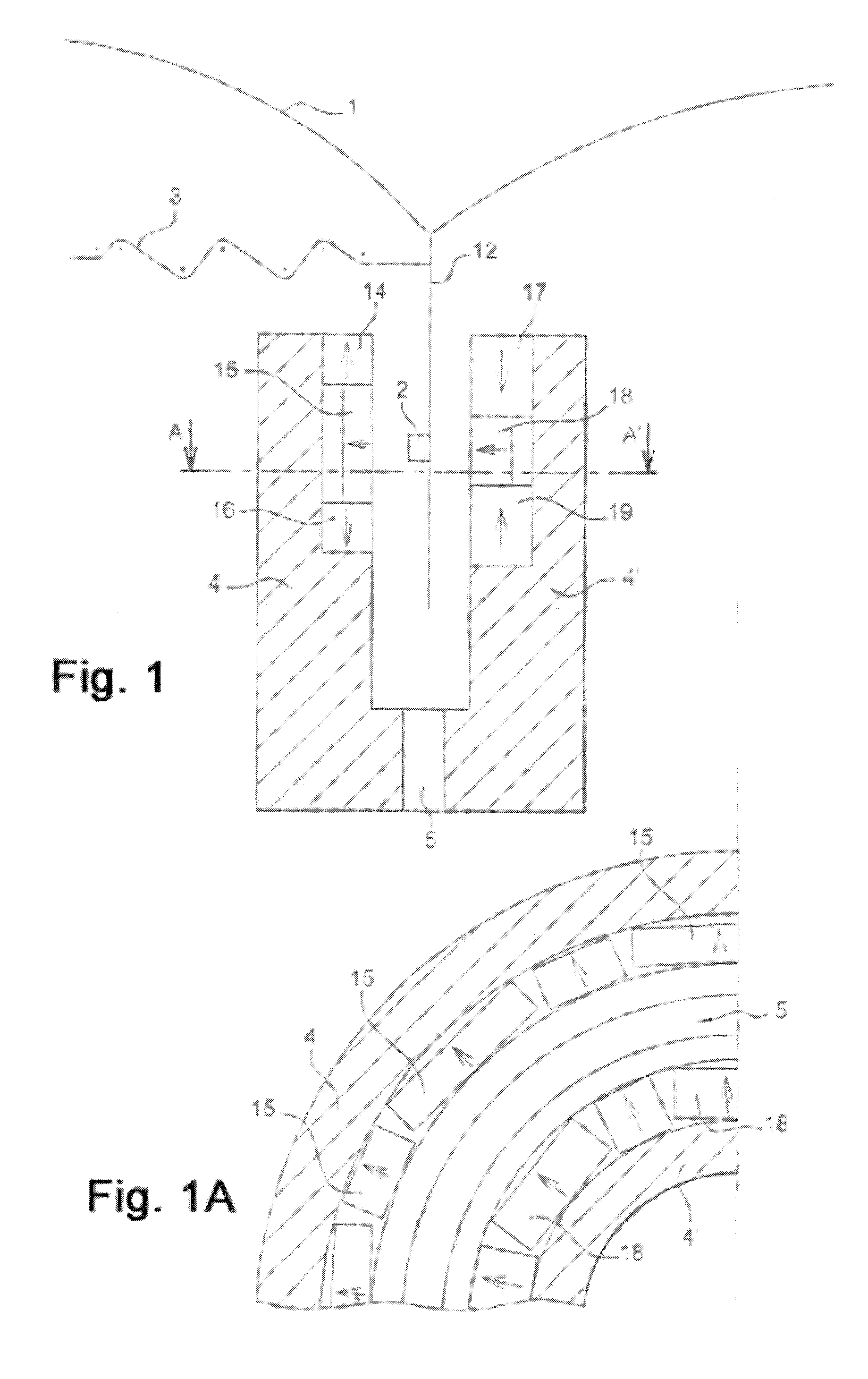
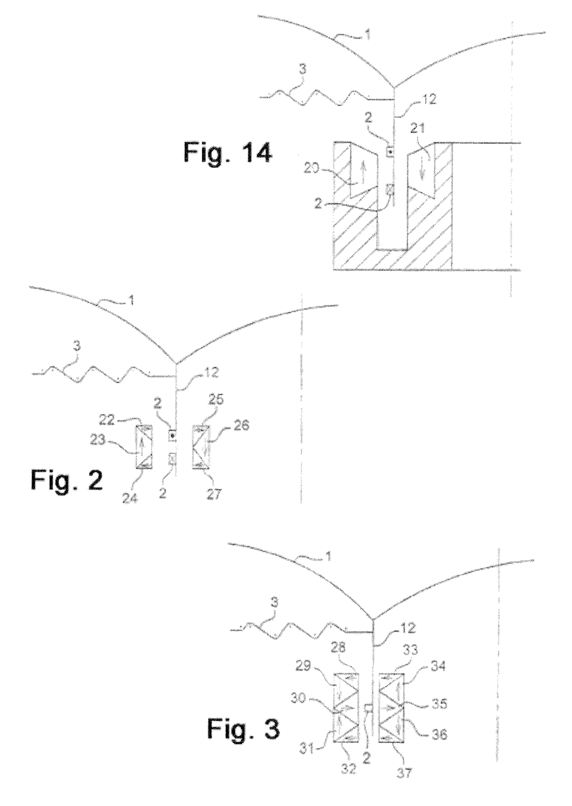
[0150]In the given description of the invention, it is to be understood that means are implemented which allow the transducer's elements to be held in a fixed relation to each other, in particular the magnets and / or the coil(s) on the mandrel, which is however moving along a vertical orientation in the vertical free space. In case of application to a loudspeaker, these means are a yoke bearing the magnets and which is in an amagnetic material (non magnetic, non ferromagnetic) and, preferably, in a light alloy or a plastic material. It will be noticed that the yoke has not always been shown in some of the appended Figures in order to simplify the latter.

[0151]The means holding the mandrel are of a classical type of direct suspension or not to the yoke, and in the latter case by mean of a cone or dome-type diaphragm. In the drawings, the application of the transducer to a loudspeaker has been considered and all the loudspeaker's elements have not been shown in detail in order to simpl...


PUM


Abstract

An electrodynamic transducer includes a frame and contains at least one electric coil which is placed in a static magnetic field and which can move about a rest position in a vertical free space. The coil(s) is wound around and fixed to a mandrel and a return member is used to return the coil-bearing mandrel to the rest position in the absence of an external bias, the straight cylinder defining an inner volume and an outer volume. The magnetic field is produced by outer and inner magnetic structures which each comprise at least one fixed permanent magnet in the form of a ring. The motor does not contain any ferromagnetic or magnetic part between the outer volume and the inner volume. At least the part of the frame that is used to fix the magnets is made from a non-ferromagnetic and non-magnetic material.

Description

BACKGROUND OF THE INVENTION[0001]The present invention relates to an electrodynamic transducer as well as the applications thereof to loudspeakers, geophones (sensor for seismograph), microphones or the like.DESCRIPTION OF THE RELATED ART[0002]Functional constructions for axisymmetric, moving coil type electrodynamic transducers, of electrodynamic loudspeaker type (electro-acoustic converter) generating acoustic waves in response to a current, or of acoustic or vibration sensor type (acoustic-electric converter) generating an electric signal in response of a mechanical stimulus, are known and numerous improvements have been proposed to increase their efficiency while reducing the distortions for high mechanical excursions.[0003]The general operating principle for axisymmetric, moving coil type loudspeakers, is based on the possibility to set in motion a cylindrical coil carrying an electric current, placed in a static magnetic field created by an annular permanent magnet whose magne...

Claims


Application Information

Patent Timeline
IPC IPC(8): H04R1/00H04R9/06H04R11/02
CPCH04R9/025H04R2209/021H04R2209/022
Inventor LEMARQUAND, GUYRICHOUX, BERNARDLEMARQUAND, VALERIE
Owner GILLES MILOT
Why Eureka
Try Eureka