Foam pump

a foam pump and foaming technology, applied in the field of foam pumps, can solve the problems of poor air admission effect, inconvenient installation and operation of foam pumps, and high inconvenient installation and operation of foam pumps, and achieve the effect of easy assembly and use, shortening the height, and reducing the height of the foam pump

Active Publication Date: 2012-02-07
TU XUFENG
View PDF12 Cites 21 Cited by
  • Summary
  • Abstract
  • Description
  • Claims
  • Application Information

AI Technical Summary

Benefits of technology

[0004]This utility patent is to provide a kind of foam pump with simple structure and fine air inlet effect and it is practical and easily assembled.

Problems solved by technology

Therefore, this structure has the defect that if the interval is too large, no one-way valve function can be achieved and if the interval is too small, it is possible to be blocked, leading to poor air admission effect.
The compression spring is directly supported between the valve body and the lower pole, making the foam pump too high and incontinent for installation and operation.
The foaming structure of such reference is too simple and the foaming effect is not ideal, while the piston structure is too complicated and inconvenient for manufacture and operation.

Method used


Image

  • Foam pump
  • Foam pump
  • Foam pump

Examples


Embodiment Construction

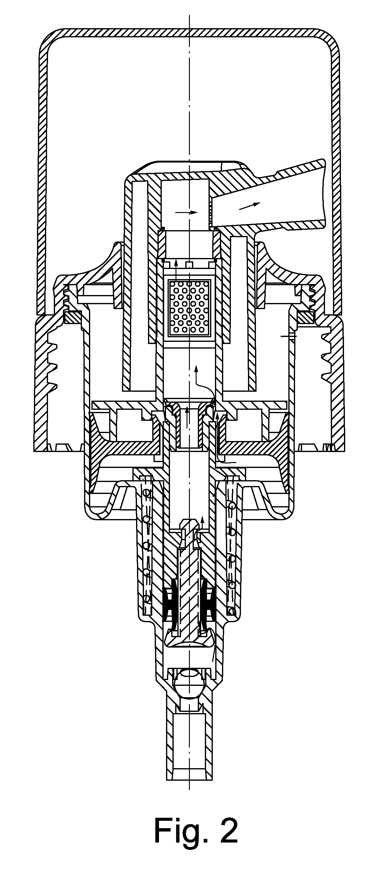
[0022]Now, description will be given below of an embodiment of this utility with reference to the accompanying drawings.

[0023]As shown in the figure, a kind of foam pump comprising a pump body 1, a large piston 2, a large piston rod 3, a small piston 4, a small piston rod 5, a over cap 6, a reticulated foam base and some other main parts, the pump body 1 is equipped with a sucker at the lower end, a glass ball 7 is equipped inside the upper part of the sucker, constituting a one-way valve, and at the same time, a ring groove 8 forms on the lower part of the pump body 1 with a U-shape section, a compression spring 9 is equipped between the ring groove 8 and the supporting ring 10 at the end of the small piston rod. And the connecting hole at the lower end of the small piston rod 5 is connected to the small piston base 11, a small piston 4 is slidably fixed at the center of the small piston base 11, the small piston 4 adopts double-valve membrane structure, the lower end of the larger...


PUM

PropertyMeasurementUnit
diameteraaaaaaaaaa
heightaaaaaaaaaa
elasticaaaaaaaaaa

Abstract

A foam pump includes a pump body, a large piston, large piston rod, a small piston, a small piston rod, a over cap and a foaming mesh. The large piston rod is equipped with a one-way valve connected with an air cavity to enable one-way air inlet from the air cavity to a gas-liquid mixing chamber. The mixed air and liquid forms a dischargeable foam.

Description

CROSS REFERENCE TO THE RELATED PATENT APPLICATION[0001]This application claims the priority of the Chinese patent application No. 200720113219.8 with filing date of Aug. 10, 2007.FIELD OF THE INVENTION[0002]This utility patent relates to a kind of foam pump.BACKGROUND OF THE INVENTION[0003]With the continuous improvement of people's living standard, foam pump has been widely used in daily cosmetic, medicines and other fields, therefore, scientists and technicians keep making new technological improvements for it. For example, Chinese patent no. 200620109913.8 “foam pump”, describes a joint, a reticulated foam meshwork mounted in the liquid inlet pipe of the joint, a screw thread whose upper part is equipped in the joint and engaged with the joint, a body whose upper opening fixed with said thread and a glass ball equipped at the liquid inlet of the body. The body includes a hollow upper pole in the thread with a shaped section, and the upper opening is located in the liquid outlet p...

Claims


Application Information

Patent Timeline
Patent Type & Authority Patents(United States)
IPC IPC(8): B67D7/76
CPCB05B7/0037B05B11/3023B05B11/3073B05B11/3087F04B15/00F04B53/108F04B53/144B05B11/0075B01F5/0698B01F3/04446B01F23/235B01F25/45243B05B11/1023B05B11/1073B05B11/1087
Inventor TU, XUFENG
Owner TU XUFENG
Why Eureka
Try Eureka