Optical system effects for computer graphics

a computer graphics and optical system technology, applied in the field of computer graphics, can solve the problems of large amount of ray tracing in rendering, and large computational time and resources, and is unsuitable for many real-time applications and non-real-time applications where computational time and resources are limited

Active Publication Date: 2012-01-31
PIXAR ANIMATION
View PDF3 Cites 12 Cited by
  • Summary
  • Abstract
  • Description
  • Claims
  • Application Information

AI Technical Summary

Benefits of technology

[0011]In an embodiment, a method of creating a optical effect in a computer graphics image includes receiving scene data defining a three-dimensional scene and receiving optical system data defining a virtual optical system including an optical system transmission function. The optical system transmission function specifies the aperture shape, light transmission characteristics, and optionally other attributes that potentially affect the appearance of circles of confusion produced by the virtual optical system....

Problems solved by technology

Conversely, other types of optical systems produce a circle of confusion with a dark center and bright edges, which some photographers consider to be aesthetically displeasing.
Because this approach requires light rays to be traced from the image samples, through different portions of the aperture, and into the scene, it c...

Method used


Image

  • Optical system effects for computer graphics
  • Optical system effects for computer graphics
  • Optical system effects for computer graphics

Examples


Embodiment Construction

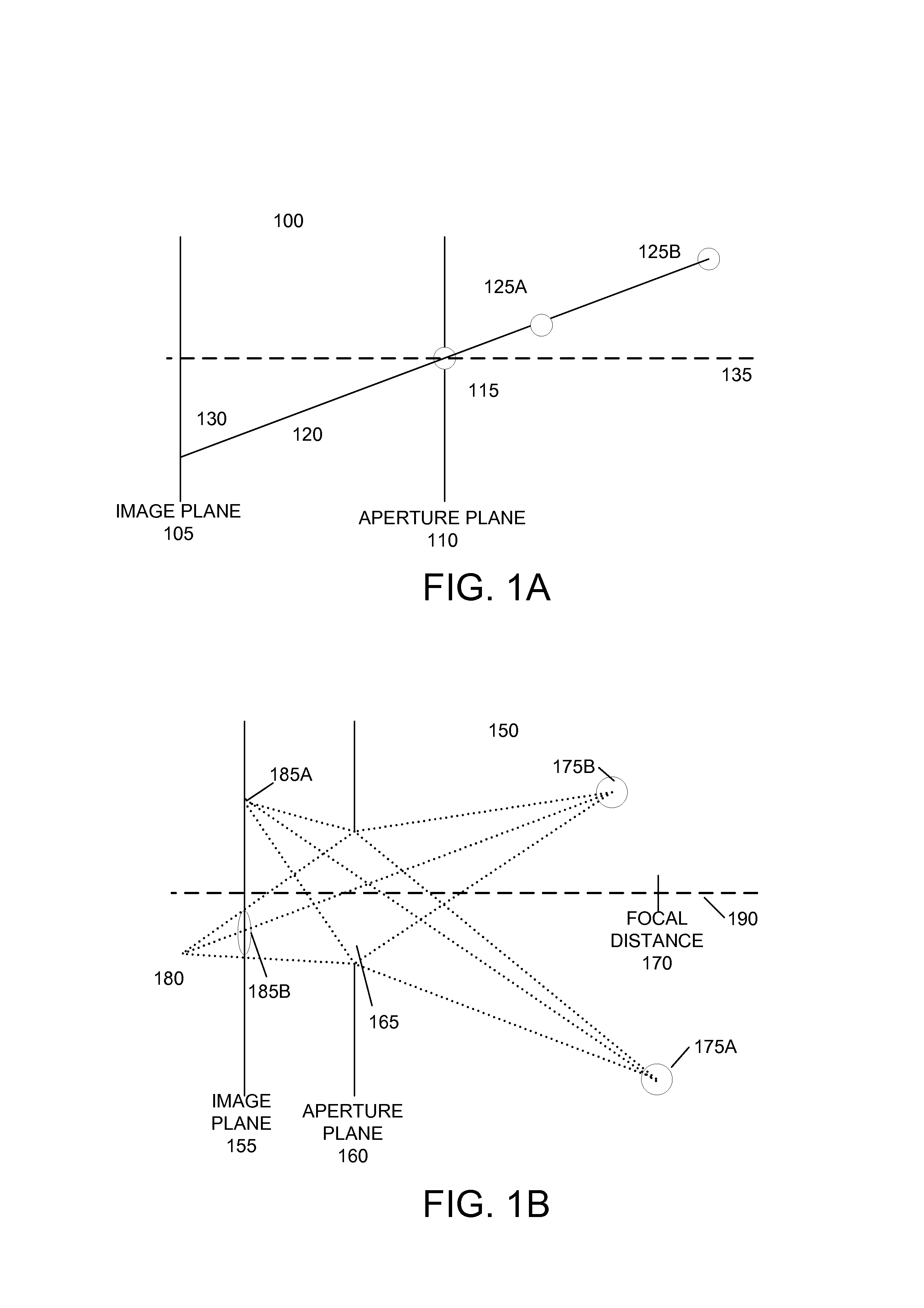
[0021]FIGS. 1A and 1B illustrate the cause of depth of field effects in real-world optical systems. FIG. 1A illustrates an example optical system 100 including an image plane 105 for receiving light that forms an image and an aperture plane 110 to admit light from a scene onto the image plane 105. Aperture plane 110 include an aperture or opening 115 to admit light from the scene. In example system 100, aperture 115 is a pinhole aperture, which ideally is infinitesimally small. System 100 has an infinite depth of field. The light from any object, regardless of its distance from the aperture plane 110, will pass through a single point, the pinhole aperture 115, and be focused perfectly on the image plane 100. For example, light from objects 125a and 125b are both focused to a single point 130 on image plane. An optical axis 135 is perpendicular to the image plane 105 and passes through the aperture 115.

[0022]In contrast, FIG. 1B illustrates an optical system 150 with a finite depth o...


PUM


Abstract

Users define the aperture shape and brightness characteristics of a virtual lens system to generate optical system effects in computer graphics images. An image sample point is associated with a aperture point within the aperture. The location of the aperture point may be based on the shape of the aperture. The image sample point value may be scaled based on a brightness value of an associated aperture point. Alternatively, the aperture point location may be based on brightness characteristics of the aperture. An optical system transmission function based on the brightness characteristics of the aperture specifies the density distribution of aperture positions within the aperture. The aperture points locations are distributed according to this optical system transmission function so that the out of focus regions or bokeh of images mimic the shape and brightness characteristics of the aperture. The aperture points, image sample points, and three-dimensional scene data are provided to a renderer to create images including optical system effects.

Description

CROSS-REFERENCE TO RELATED APPLICATIONS[0001]This application claims priority to U.S. Provisional Patent Application No. 60 / 940,380, filed May 25, 2007, which is incorporated by reference herein for all purposes.BACKGROUND OF THE INVENTION[0002]The present invention relates to the field of computer graphics, and in particular to methods and apparatus for creating, modifying, and using components to create computer graphics productions. Many computer graphic images are created by mathematically modeling the interaction of light with a three dimensional scene from a given viewpoint. This process, called rendering, generates a two-dimensional image of the scene from the given viewpoint, and is analogous to taking a photograph of a real-world scene. Animated sequences can be created by rendering a sequence of images of a scene as the scene is gradually changed over time. A great deal of effort has been devoted to making realistic looking and artistically compelling rendered images and a...

Claims


Application Information

Patent Timeline
IPC IPC(8): G06T15/10
CPCG06T15/10G06T15/50
Inventor DUFF, THOMAS DOUGLAS SELKIRK
Owner PIXAR ANIMATION
Why Eureka
Try Eureka