Centrifuge adapter and closure

a technology for centrifuges and adapters, applied in centrifuges, laboratory glassware, caps, etc., can solve problems such as potential leakage on the inner side, and achieve the effects of reducing the distortion of the sealing area, eliminating all unnecessary support interfaces, and dimensional toleran

Active Publication Date: 2012-01-31
THERMO ELECTRONICS LED GMBH
View PDF18 Cites 15 Cited by
  • Summary
  • Abstract
  • Description
  • Claims
  • Application Information

AI Technical Summary

Benefits of technology

[0008]According to one aspect of the present invention, an adapter and a closure are specifically designed so as to minimize distortion of the sealing area by eliminating all unnecessary support interfaces and thus their associated dimensional tolerances. The closure is preferably manufactured at least partly from high-strength, transparent plastic so that operating personnel can detect, even before opening the adapter, whether the sample container located in the adapter is damaged and whether any potentially biologically hazardous material has leaked into the internal space of the adapter.
[0012]According to yet another aspect of the present invention, an interrupted bayonet type closure is used in order to avoid both having to decant fluid over the closure retainer threads, in the case of a broken sample container, and also having to use multiple closure turns to effect a seal. The completeness of the closure and open position is determined by positive stops. A conventional piston type O-ring seal does not allow easy insertion of a closure due to the required O-ring cross-sectional squeeze needed to effect a seal and due to the cumulative fit tolerances. In order to overcome this, a spring element is incorporated to provide a transverse squeeze to effect the seal. In one embodiment the transverse squeeze is applied by a threaded element. The resulting seal is dynamic in that the greater the pressure to be sealed, the greater the resulting sealing force. A flexible ring is also incorporated in the closure to completely encapsulate the O-ring thus eliminating the potential for the O-ring material to extrude from the O-ring groove.
[0013]According to another aspect of the present invention, the adapter is manufactured at least partly from metal or a metal alloy. By the use of metal or a metal alloy, a self-supporting structure of the adapter is ensured and the stability of the adapter is improved. A safer operation of the rotor is thus possible on the whole. Examples of the metals that can be used include steel, aluminum or titanium.
[0014]Alternatively or additionally, the adapter is manufactured at least partly from carbon fiber composite material. The weight of the adapter can thus be reduced and simultaneously a high stability can be achieved. It is preferred to manufacture those areas of the adapter that are designed using carbon fiber composite design using “winding technology.” Here the adapter or portions thereof made of carbon fibers are wound around a reel core. The adapter can basically be manufactured completely from metal or from carbon fiber composite material. In addition, a combination of both the materials is also possible. A safe centrifugation is ensured even in the manufacturing process using the carbon fiber composite design.
[0015]For increasing the stability of the adapters and thus for improving the safety of the centrifugation, it is expedient for the adapter to be built at least in certain places from an inner jacket and an outer jacket resting against the inner jacket. This two-layer design (hybrid design) further improves the adapter stability. The adapter can basically be designed completely from two layers or can have the two-layer design only in certain places for reinforcing certain adapter parts. In this embodiment, the inner jacket is preferably formed out of a sleeve, also called “liner.” The liner can be manufactured from metal or plastic and can have varying wall thicknesses in the rotor radial direction and in the rotor circumferential direction. The outer jacket is preferably manufactured from carbon fiber composite material. The carbon fibers are wound around the liner. The liner can basically fill out the entire inner surface of the adapter or can be fitted only in certain portions for reinforcing the adapter.
[0016]In addition, it is preferred to design a part of the closure assembly such that it is integrated into the inner jacket. Due to this, the number of individual parts of the adapter can be reduced, thus facilitating design and handling. For the integrated design, it is expedient that one liner is disposed at least in the area of the open end of the adapter. It is preferred to design the bottom with the associated thread in the liner. Furthermore, the flange can also be designed such that it is integrated into the liner.

Problems solved by technology

In conventional designs of sample containers, because of smaller neck diameters the inner side is also under fluid pressure resulting in potential leaks on the inner side.

Method used


Image

  • Centrifuge adapter and closure
  • Centrifuge adapter and closure
  • Centrifuge adapter and closure

Examples


Embodiment Construction

[0031]The invention will now be described with reference to the drawing figures, in which like reference numerals refer to like parts throughout. An embodiment according to the present invention provides an adapter and a closure specifically designed to minimize distortion of the sealing area by eliminating all unnecessary support interfaces and thus their associated dimensional tolerances.

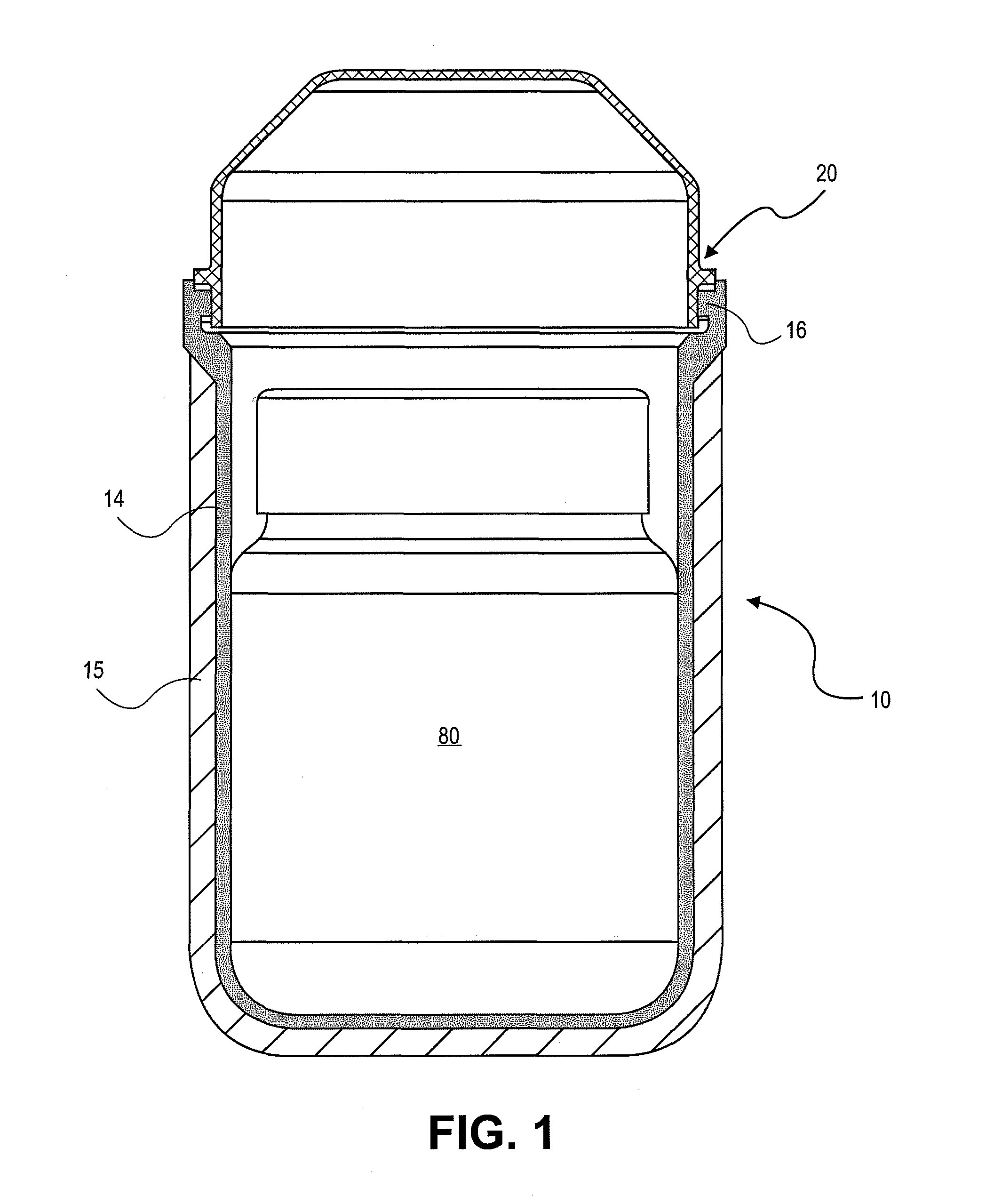
[0032]FIG. 1 illustrates the cut lateral view of an adapter 10. The adapter 10 is closed with a closure assembly 20 and is sealed in a bio-proof manner. In the interior of the adapter 10, a sample container 80 is disposed that can be inserted into the adapter 10 with positive locking. Furthermore, it must be understood that the adapter 10 is manufactured from a 2-layer design and comprises an inner jacket 14 and an outer jacket 15 that rests against the inner jacket. The inner jacket is formed out of a liner that is manufactured from metal and around which carbon fiber material forming the outer j...


PUM


Abstract

An adapter for taking up a sample container and for use in a laboratory centrifuge rotor, the adapter including a closed end, an opened end and closure assembly that releasably seals the opened end. The closed end and the opened end can be of a certain diameter. The adapter can also be a certain shape. The closure assembly can also include a handle, flange, a hold down ring, a sealing ring and bottom support for the sealing ring, hold down ring, flange and handle.

Description

CROSS-REFERENCE TO RELATED APPLICATIONS[0001]The present application claims priority of German Application No. 10 2004 062 233.7, filed Dec. 23, 2004, the entire contents of which are incorporated herein by reference.FIELD OF THE INVENTION[0002]The present invention relates to an adapter for taking up a sample container and for use in a laboratory centrifuge. The term “adapter” in the following description refers to sleeve-type receptacles into which sample containers can be inserted. The adapters can in turn be inserted into centrifuge rotors.BACKGROUND OF THE INVENTION[0003]A centrifuge rotor is a relatively massive member in which a liquid sample is exposed to a centrifugal force field. The liquid sample is carried in a sample container. For supporting the sample container and for stabilizing the rotor, sleeve-type adapters are known that are designed for taking up the sample containers. The adapters can in turn be inserted into a vertical or fixed angle centrifuge rotor. Such ad...

Claims


Application Information

Patent Timeline
Patent Type & Authority Patents(United States)
IPC IPC(8): B04B5/04B65D41/04
CPCB01L9/06B04B5/0414B01L3/5021B01L2200/025B04B2005/0435B04B5/02B04B7/085
Inventor ROMANAUSKAS, WILLIAM A.SHEERAN, EDWARD T.EIGEMEIER, FRANK
Owner THERMO ELECTRONICS LED GMBH
Why Eureka
Try Eureka