
Torque resistant terminal block element

a terminal block and torque-resistant technology, applied in the direction of clamped/spring connections, electrical equipment, connections, etc., can solve the problems of difficult visual differentiation, unusable screw terminals, -type screw terminals, etc., and achieve greater clamping forces, greater pulling force, and greater force

Active Publication Date: 2012-01-31
ILLINOIS TOOL WORKS INC
View PDF7 Cites 16 Cited by
  • Summary
  • Abstract
  • Description
  • Claims
  • Application Information

AI Technical Summary

Benefits of technology

[0011]The present inventor has developed screw terminals and corresponding terminal blocks that can apply larger clamping forces to wires while avoiding numerous problems that have previously been associated with trying to apply higher torques to the screws. The particular configuration(s) of the screw terminal and terminal block allow the machine screws to be tightened more than could previously be done, without compromising the interaction of the nut, the screw, and the clamping wall.
[0023]It is thus another object of the invention to provide a terminal block that can prevent the screw from being completely removed from the capture nut. It is another object of the invention to provide a terminal block with a robust support that can hold the screw terminal in a vertical direction, allowing move downward force to be applied to the screw when rotating it, which may result in more torque being applied to the screw without the tool slipping out of the screw.

Problems solved by technology

Thin or short nuts have relatively few threads so that tightening the screw beyond a certain extent may strip the threads from the nut, rendering the screw terminal unusable.
Furthermore, the inventor has recognized that terminal blocks having channel-type screw terminals which require the nuts to be pulled up toward the screw head can be difficult to visually differentiate from those having screw terminals that require the nuts to be pushed away from the screw head.

Method used


Image

  • Torque resistant terminal block element
  • Torque resistant terminal block element
  • Torque resistant terminal block element

Examples


Embodiment Construction

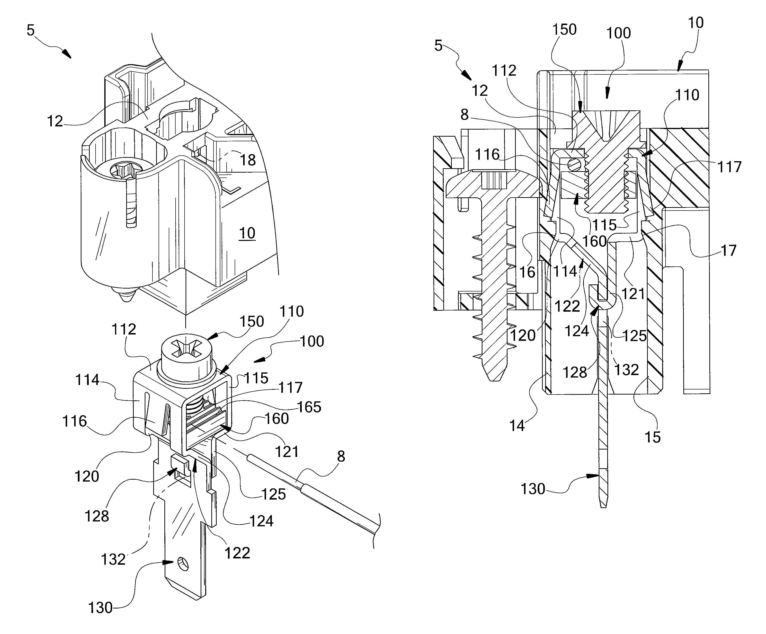
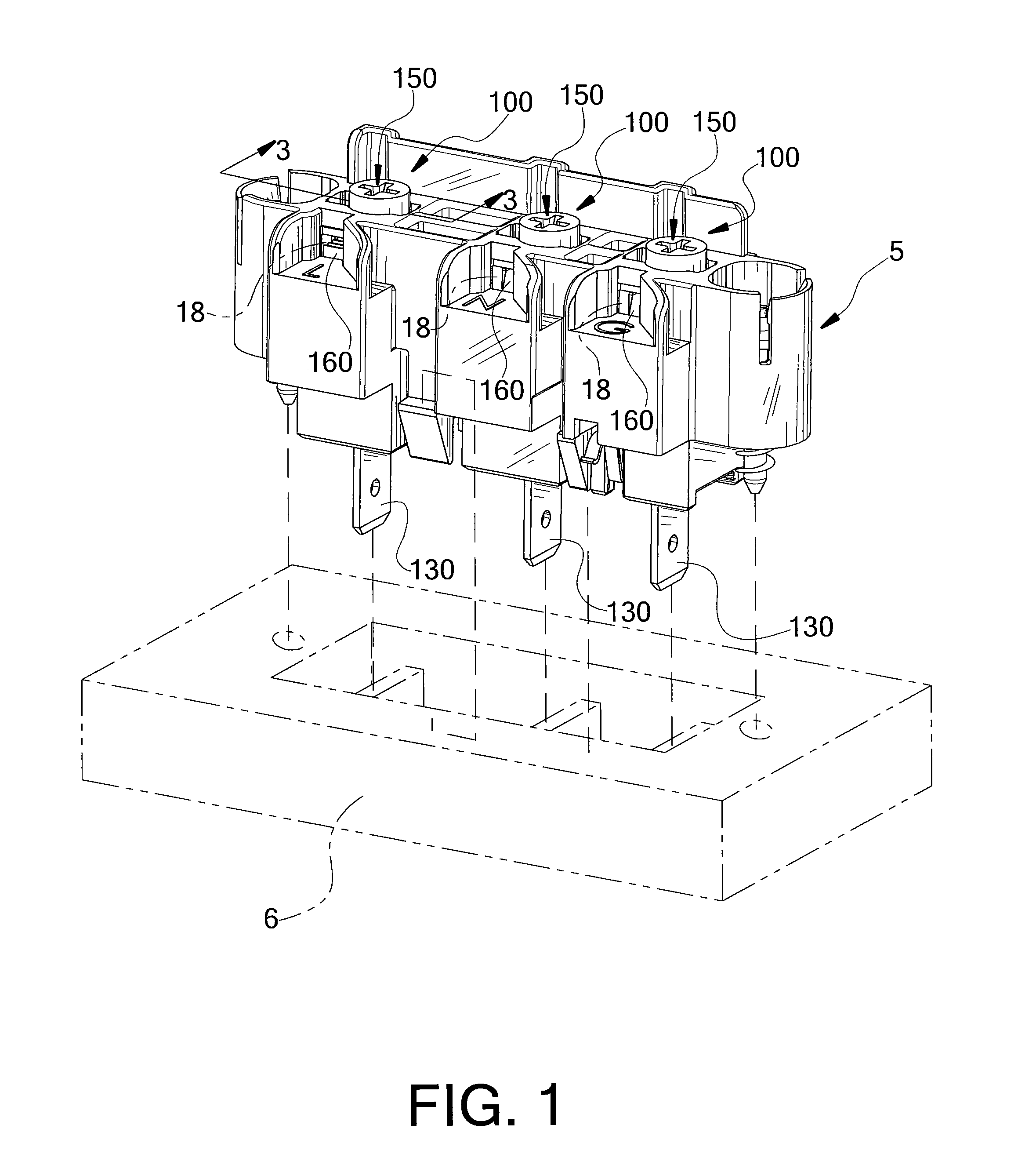
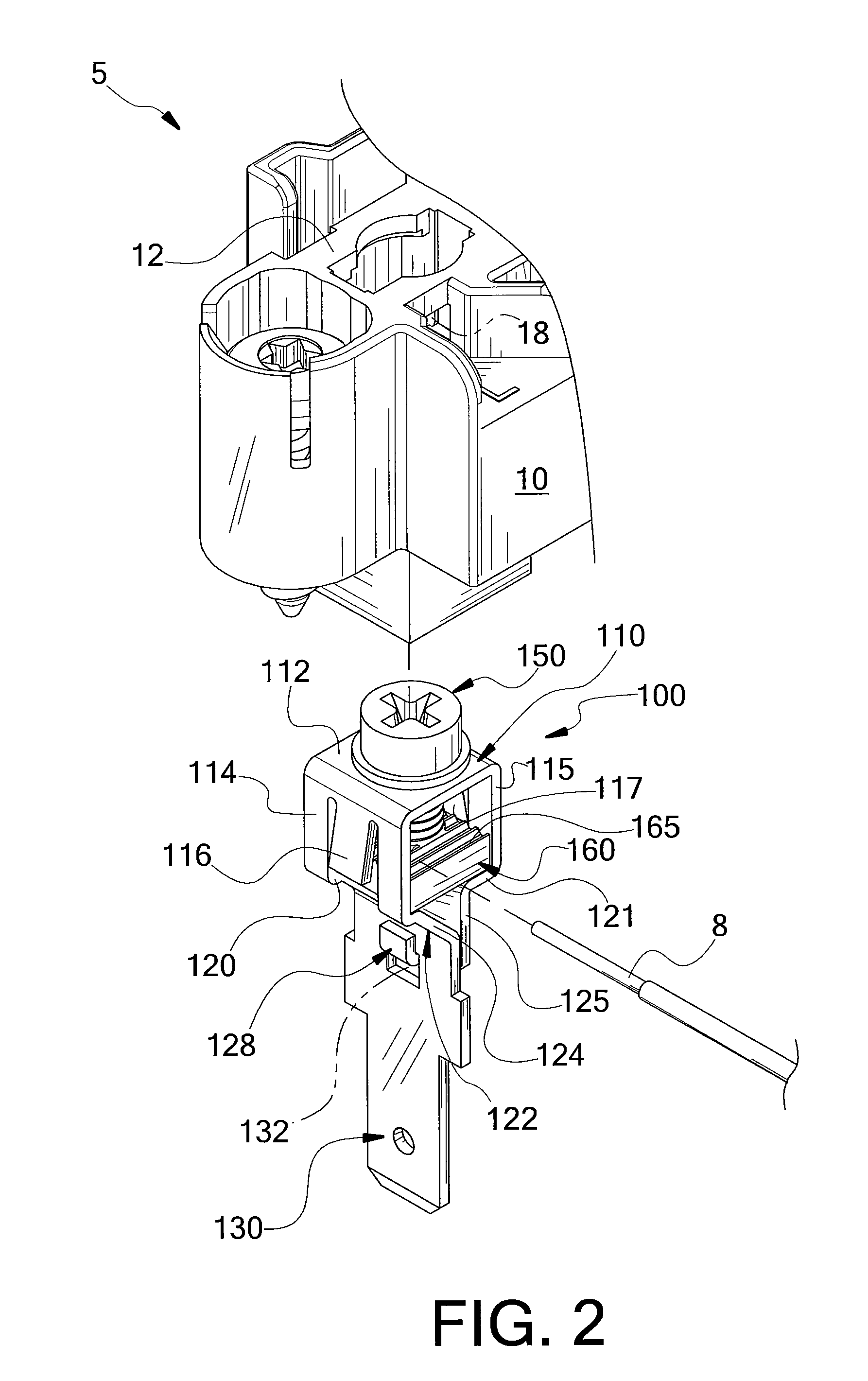
[0030]FIGS. 1 and 2 each shows a terminal block 5 or portion thereof that is configured for electrically connecting wires 8 to a receptacle 6 in an electronic device or system. Terminal block 5 includes a housing 10 which holds at least one screw terminal 100. As shown in FIG. 2, each screw terminal 100 includes a generally box-shaped frame 110 from which a conductive blade 130 extends and that has open ends and an inner space that holds a captured nut 160 that is movable along a screw 150, explained in greater detail elsewhere herein.

[0031]Referring now to FIG. 1, this particular embodiment of housing 10 holds three screw terminals 100. The three illustrated screw terminals 100 are provided to connect wires 8 to the line “L”, neutral “N”, and ground “G” conductors of an electrical circuit(s). This configuration can be used with, for example, circuits carrying about 20 A at about 300V, or others, based on the particular end-use configuration of the electronic device or system.

[0032]...


PUM


Abstract

A screw terminal and a terminal block incorporating the same provides a mechanically a screw terminal frame with a closed perimeter that resists deformation of the terminal frame when a captured nut is being clamped against a wire within the terminal frame, allowing the captured nut to be clamped more tightly against the wire. Sidewalls of the terminal frame may include tabs that engage ledges of a block housing to support the screw terminal and the captured nut may have surface irregularities upon the surface that engages the wire and to improve electrical contact therebetween and resist mechanical pull out of the wire.

Description

CROSS REFERENCE TO RELATED APPLICATION[0001]This Non-Provisional Application claims benefit to U.S. Provisional 61 / 254,092 filed Oct. 22, 2009 and hereby incorporated by reference.FIELD OF THE INVENTION[0002]The present invention relates generally to electrical terminals providing a releasable mechanical and electrical connection to a current-carrying wire and, in particular, to a screw terminal in which the connection is made by tightening a machine screw.BACKGROUND OF THE INVENTION[0003]Electrical screw terminals, normally as part of a terminal block, provide a versatile and reliable method of making electrical connections. The quality of the connection to a screw terminal, both in terms of providing low electrical resistance and high mechanical stability, is increased by increasing the clamping force of the nut on the wire. Increased clamping force may be obtained by applying greater torque to the machine screw. However, known screw terminals and terminal blocks are limited with ...

Claims


Application Information

Patent Timeline
Patent Type & Authority Patents(United States)
IPC IPC(8): H01R9/22
CPCH01R4/304H01R4/34H01R9/24H01R9/2475
Inventor CLAPROOD, JR., EDWARD J.
Owner ILLINOIS TOOL WORKS INC
Learn More