
Flow controller, flow measuring device testing method, flow controller testing system, and semiconductor manufacturing apparatus

a flow controller and flow measurement technology, applied in process and machine control, liquid/fluent solid measurement, instruments, etc., can solve the problems of accuracy with which the flow controllers control the flow rate, and achieve the effect of shortening the time required for the test and high accuracy

Active Publication Date: 2012-01-31
HORIBA STEC CO LTD
View PDF11 Cites 21 Cited by
  • Summary
  • Abstract
  • Description
  • Claims
  • Application Information

AI Technical Summary

Benefits of technology

The present invention relates to a method for testing flow controllers in semiconductor manufacturing processes. The conventional method involves a long wait time for the test to start, due to the time required for the pressure in the system to stabilize. The new method involves a flow controller testing method that involves comparing the actual flow rate measurement of a testing-standard flow controller with the target flow rate determined by the testing-subject flow controller. This method helps to shorten the time required for the test and ensures high accuracy.

Problems solved by technology

Since problems in the accuracy with which the flow controllers control flow rate give rise to product defects in the semiconductor wafers, flow rate tests are carried out at regular or irregular intervals in order to verify whether or not the flow controller is able to control the flow rate as designed.

Method used


Image

  • Flow controller, flow measuring device testing method, flow controller testing system, and semiconductor manufacturing apparatus
  • Flow controller, flow measuring device testing method, flow controller testing system, and semiconductor manufacturing apparatus
  • Flow controller, flow measuring device testing method, flow controller testing system, and semiconductor manufacturing apparatus

Examples


first embodiment

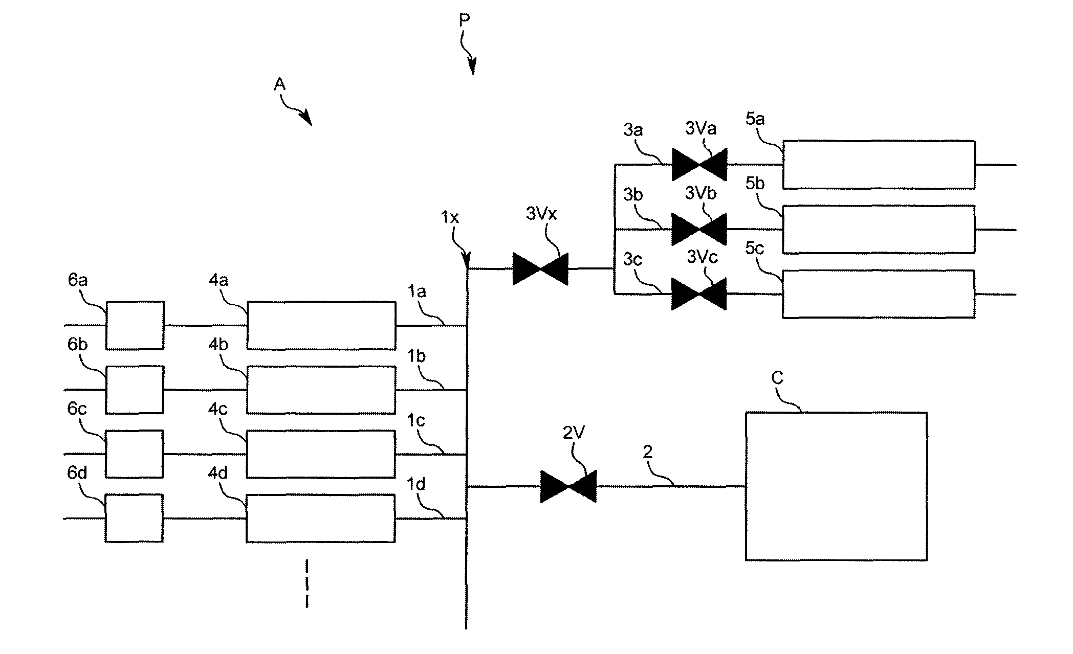
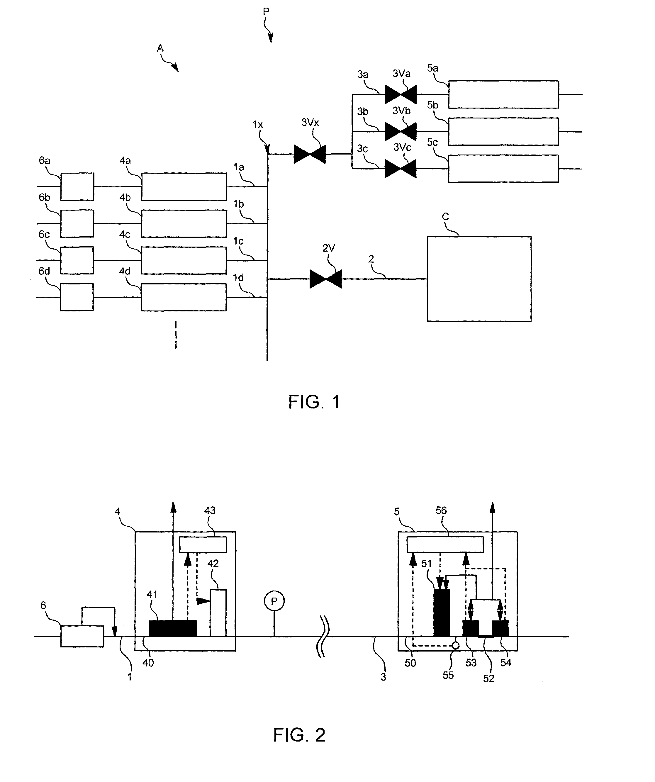
[0039]The system for testing a flow controller A of this embodiment is, as shown in FIG. 1, a part of a semiconductor manufacturing apparatus P and used for testing a flow controller to control various gases supplied to a process chamber C for the semiconductor. Specifically, this testing system A comprises gas supply lines 1, 1b, . . . (hereinafter collectively referred to as “a gas supply line 1”) where various kinds of gas for manufacturing semiconductor such as a process gas or an etching gas flows, a line for a chamber 2, and lines for test 3a, 3b, 3c (hereinafter collectively referred to as “a line for test 3”) arranged in parallel on a downstream side of a converging section where the gas supply lines 1 converge, a flow controller as being an object to be tested 4a, 4b, . . . (hereinafter collectively referred to as “a testing-subject flow controller 4”) each of which is arranged on the gas supply line 1 respectively, a flow controller as being a reference 5a, 5b, 5c (hereina...

second embodiment

[0073]Next, a second embodiment of this invention will be explained. The same components as those in the first embodiment are denoted by the same reference codes as those in this embodiment.

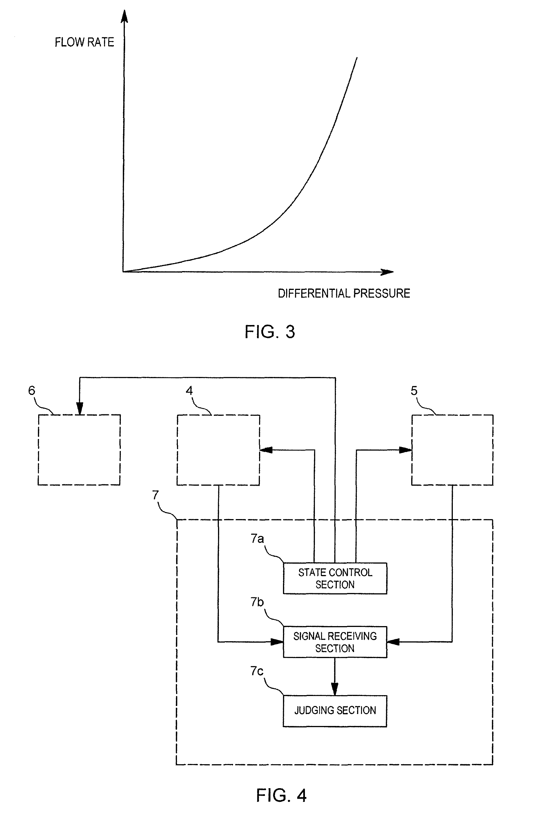
[0074]In this second embodiment, as shown in FIG. 7, only a single testing-standard flow controller 5 is used and a linear resistive element (an orifice) 8 is arranged on the downstream side of the testing-standard flow controller 5. As shown in FIG. 8, a relationship between a flow rate flowing inside the linear resistive element 8 and a pressure differential between both ends of the linear resistive element 8 is linear and an effective flow rate volume of the linear resistive element 8 is bigger than that of the non-linear resistive element 52. A reference code BL in FIG. 7 is a bypass line to introduce a fluid into the linear resistive element 8 without using the testing-standard flow controller at a time of conducting a test by the use of the linear resistive element 8.

[0075]In addition, an i...


PUM


Abstract

A testing method for testing a flow controller with high accuracy by shortening as much as possible the time required for the test including the wait time. A testing-subject flow controller and a testing-standard flow controller are arranged in that order in series from the upstream side in a flow channel through which a fluid whose flow is to be controlled flows. In a flow-uncontrolled state in which the valve of the testing-subject flow controller is practically in the full-open state, and with the fluid flow controlled to a predetermined flow rate by the testing-standard flow controller, whether the actual flow-rate measurement according to the testing-subject flow controller falls within a predetermined range of actual flow-rate measurements according to the testing-standard flow controller is determined.

Description

FIELD OF THE ART[0001]This invention relates to methods of testing flow controllers that in semiconductor-manufacturing and similar processes control the flow of fluids including gases and liquids.BACKGROUND ART[0002]In semiconductor-wafer and like manufacturing, conventionally flow controllers that control the flow rate of gas supplied to the chamber are employed. Since problems in the accuracy with which the flow controllers control flow rate give rise to product defects in the semiconductor wafers, flow rate tests are carried out at regular or irregular intervals in order to verify whether or not the flow controller is able to control the flow rate as designed.[0003]Specifically, the test is conducted as follows.[0004]In a case where, for example, a flow rate test is conducted on a thermal mass flow controller (hereinafter termed a “thermal MFC 101”) comprising a sensor section 101a and a control valve 101b, as shown in FIG. 11, a pressure differential mass flow meter (hereinafte...

Claims


Application Information

Patent Timeline
Patent Type & Authority Patents(United States)
IPC IPC(8): G01P21/00
CPCG05D7/0635G05D7/03G05D7/00
Inventor YASUDA, TADAHIRO
Owner HORIBA STEC CO LTD
Learn More