
Data signal system

a data signal and data technology, applied in the field of receivers, can solve problems such as interference or anomalies, user may be presented with low quality information, interfere with proper demodulation of rds signal,

Active Publication Date: 2012-01-17
NXP USA INC
View PDF18 Cites 10 Cited by
  • Summary
  • Abstract
  • Description
  • Claims
  • Application Information

AI Technical Summary

Benefits of technology

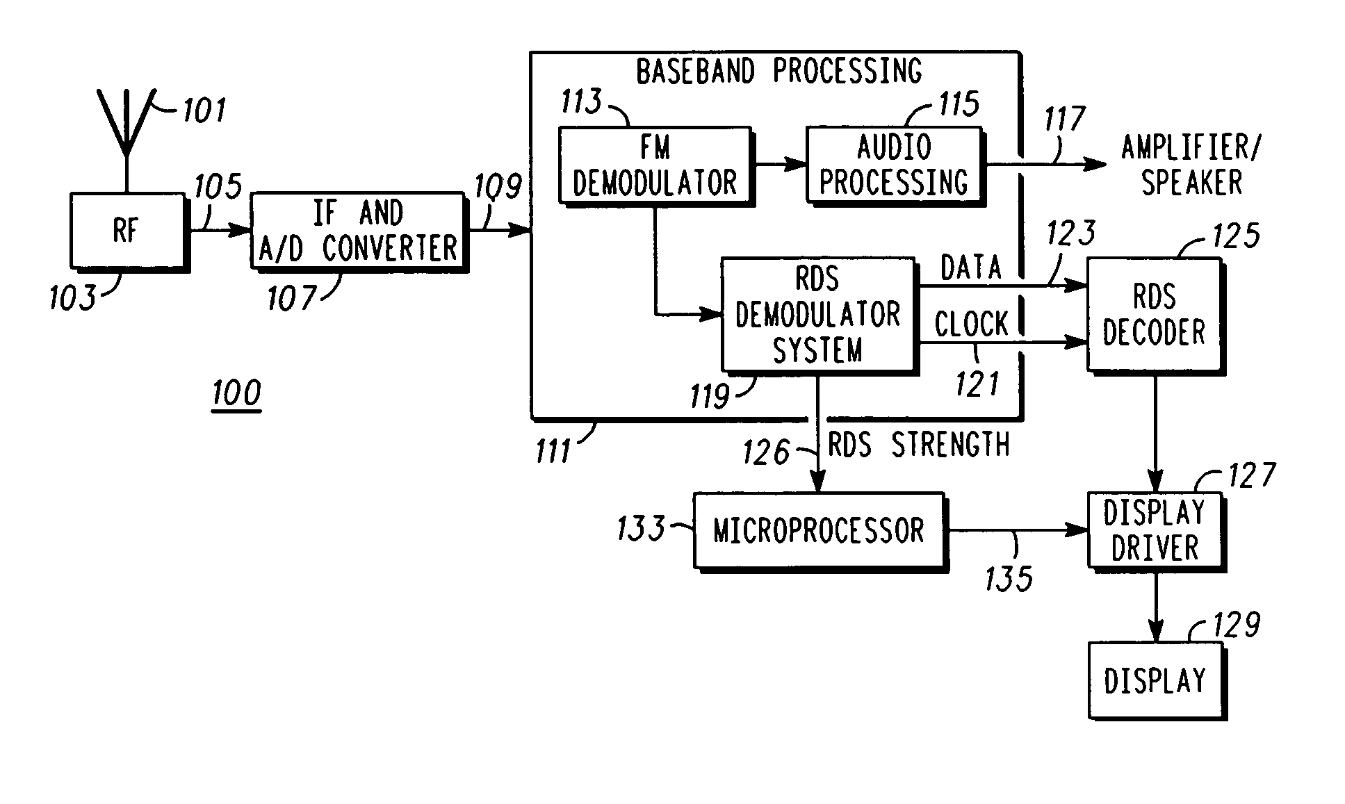
The present invention relates to techniques and apparatus for receivers that are designed to demodulate signals that include embedded data signals, such as RDS signals. The invention aims to mitigate interference and other anomalies that may occur with these signals, including interference from other FM signals and noise introduced during demodulation. The invention provides methods and apparatus for reducing interference and improving the quality of the RDS signal demodulation process. The invention can be applied to receivers in various transportation vehicles and other equipment that receive and process FM signals, including portable and home-based receivers. The invention is particularly useful in addressing issues related to loss of signal and interference in FM signals.

Problems solved by technology

Various problems (interference or anomalies) have been observed in radios using RDS.
For example, when a signal rapidly deteriorates the user may be presented with low quality information due to the weak signal conditions.
In those instances when the FM signal combined with noise results in an amplitude modulated (AM) signal that exceeds 100% modulation, large impulse noise components may be introduced into the RDS signal after FM demodulation and thus interfere with proper demodulation of the RDS signal.
This results in another form of interference in attempts to properly demodulate the RDS signal.

Method used


Image

  • Data signal system
  • Data signal system
  • Data signal system

Examples


Embodiment Construction

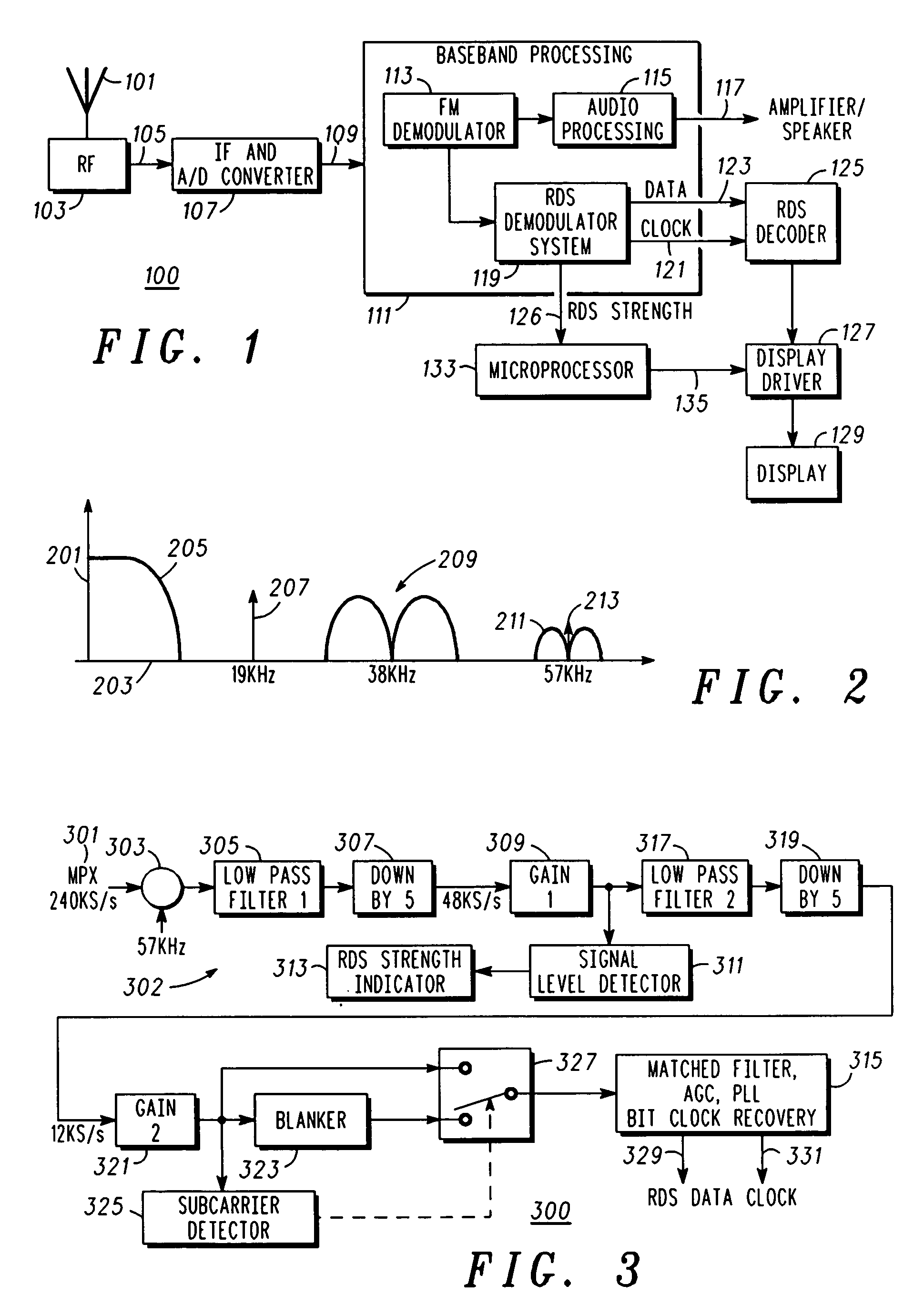
[0011]In overview, the present disclosure concerns receivers, and more specifically techniques and apparatus for use in a receiver arranged and configured to demodulate signals including embedded data signals, e.g. a radio data system (RDS) signal, in order to mitigate various forms of interference or other anomalies that may be associated with such signals and corresponding demodulation systems. More particularly various inventive concepts and principles embodied in methods and apparatus, e.g., receivers, radio data systems, demodulation systems, integrated circuits, and the like for receiving, demodulating, decoding, etc. data signals, such as RDS signals, while mitigating interference, will be discussed and disclosed.

[0012]The apparatus in various embodiments of particular interest may be or include receivers or the like for receiving and otherwise processing broadcast Frequency Modulated (FM) signals or similar signals that comprises the normal broadcast signal together with a d...


PUM


Abstract

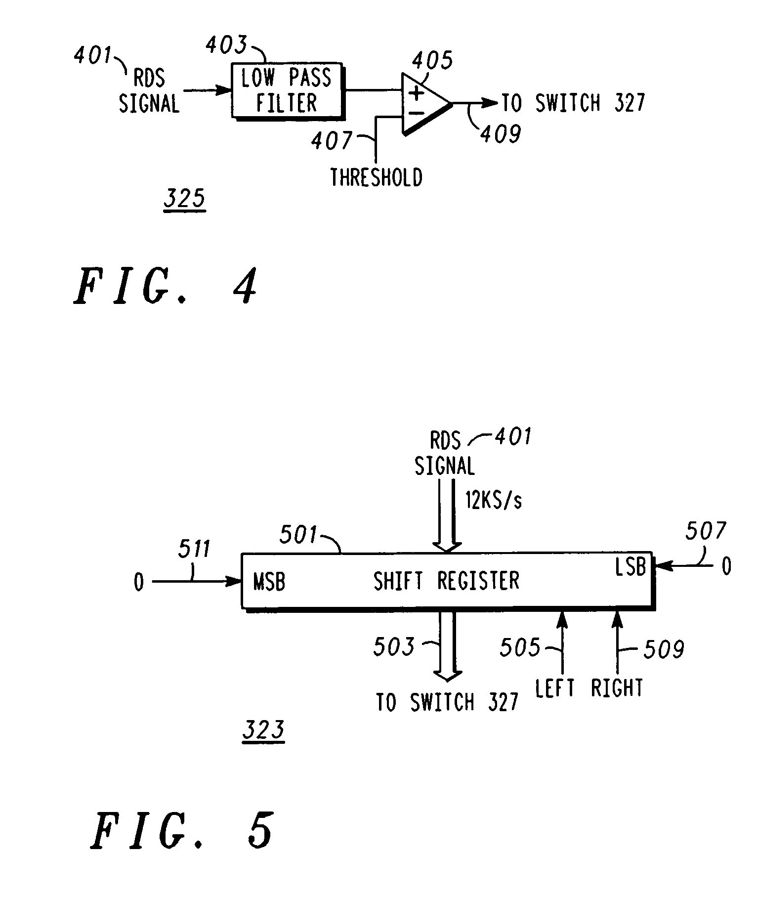
A demodulation system for Radio Data System (RDS) signals in a receiver includes a quadrature mixer (303) configured to convert a RDS signal at an input frequency directly to a base band RDS signal, a single filter (305) configured to filter the base band RDS signal to provide a RDS signal, and a signal level detector (311) configured to provide an indication of a level of the RDS signal (313), a demodulator (315) configured to demodulate the RDS signal and provide RDS data, the RDS data corresponding to information for user consumption, where the indication is used for selectively interrupting the user consumption when the level of the RDS signal is unsatisfactory. Other aspects of the RDS and corresponding methods include interference mitigation and include a blanker (323) configured to remove impulse noise from a RDS signal to provide the RDS signal without impulse noise and a demodulator (315) coupled to the blanker and configured to demodulate the RDS signal to provide data corresponding to information for user consumption.

Description

FIELD OF THE INVENTION[0001]This invention relates in general to receivers and more specifically to techniques and apparatus in receivers that are arranged and constructed for receiving radio data system signals.BACKGROUND OF THE INVENTION[0002]The Radio Data System (RDS) is used to broadcast information together with Frequency Modulated (FM) radio signals for automobile radios as well as home based FM receivers. The FM broadcast signal with the embedded RDS signal is known as a multiplex (MPX) signal. This signal includes information such as program identification including type of program (news, music, etc.), traffic information, title of a song, artist, and the like. In some automotive radios, the radio can switch to another station with the same programming when a given signal deteriorates. The RDS signal may also be accompanied by a Motorist Information System (referred to commonly as ARI) signal. Both the RDS and ARI signals are relatively narrowband signals spaced at 57 KHz (...

Claims


Application Information

Patent Timeline
Patent Type & Authority Patents(United States)
IPC IPC(8): H04B1/18H04B7/00
CPCH04H40/18H04H20/34H04H2201/13
Inventor SU, JIE
Owner NXP USA INC
Learn More