
Automatic calibration in high-speed serial interface receiver circuitry

a receiver circuit and serial interface technology, applied in pulse manipulation, instruments, pulse techniques, etc., can solve the problems of introducing further loss and/or distortion, affecting the accuracy of the initial reception and processing of the incoming signal, and the loss and/or distortion of the received signal

Active Publication Date: 2012-01-17
ALTERA CORP
View PDF5 Cites 7 Cited by
  • Summary
  • Abstract
  • Description
  • Claims
  • Application Information

AI Technical Summary

Benefits of technology

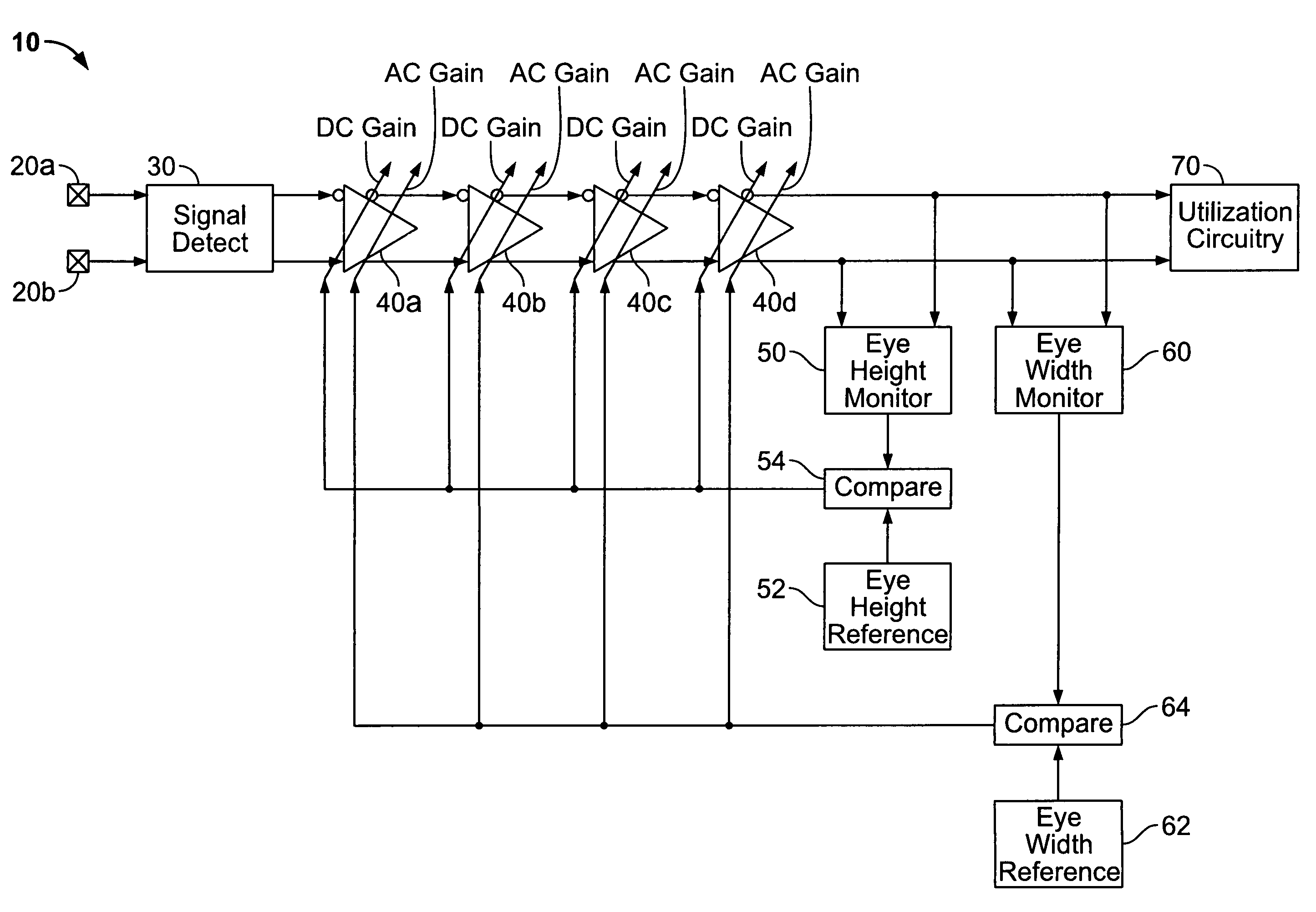
The invention provides circuitry and methods for receiving high-speed serial data signals and automatically compensating for various types and amounts of loss and distortion in the signal. The circuitry includes adjustable equalizer circuitry with controllably variable gain based on attributes of the signal, such as eye height or width. The technical effect of the invention is to improve the quality and reliability of serial data transmission.

Problems solved by technology

The received signal will also typically have been subject to some loss and / or distortion during transmission.
In addition, the receiver circuit components that initially receive and process the incoming signal may not be perfect, and they may themselves tend to introduce further loss and / or distortion before passing the received signal on to downstream circuitry such as the above-mentioned CDR circuitry.
Such loss and / or distortion increases the difficulty of accurately recovering data from the serial data signal at the receiver.
This difficulty is further increased by such design objectives as reduced voltage or power of the transmitted signal, increased data rate of that signal, etc.

Method used


Image

  • Automatic calibration in high-speed serial interface receiver circuitry
  • Automatic calibration in high-speed serial interface receiver circuitry
  • Automatic calibration in high-speed serial interface receiver circuitry

Examples


Embodiment Construction

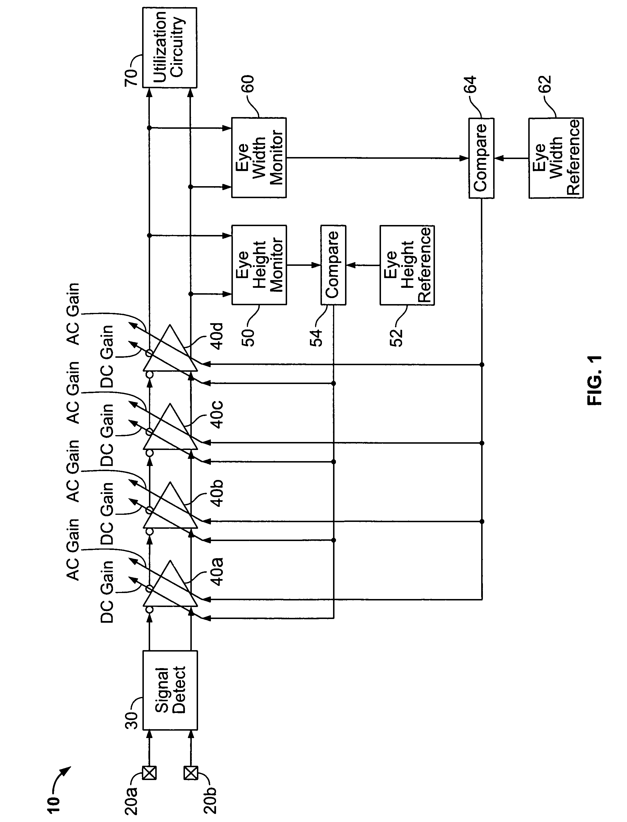
[0012]As shown in FIG. 1, illustrative receiver circuitry 10 in accordance with the invention includes a pair of input terminals 20a and 20b for receiving a high-speed serial data signal in differential form. As is well known to those skilled in the art, this means that the high-speed serial data signal is actually a pair of signals that are the logical complement of one another. For example, a binary 1 data bit may be indicated or signalled by the signal applied to input terminal 20a having a relatively high voltage while the signal applied to input terminal 20b has a relatively low voltage. In such a case, a binary 0 data bit is indicated or signalled by the signal applied to input terminal 20a having a relatively low voltage while the signal applied to input terminal 20b has a relatively high voltage.

[0013]The signals applied to input terminals 20a and 20b are applied to signal detect circuit 30, which acts, for example, as input buffer circuitry for receiver 10. Signal detect ci...


PUM


Abstract

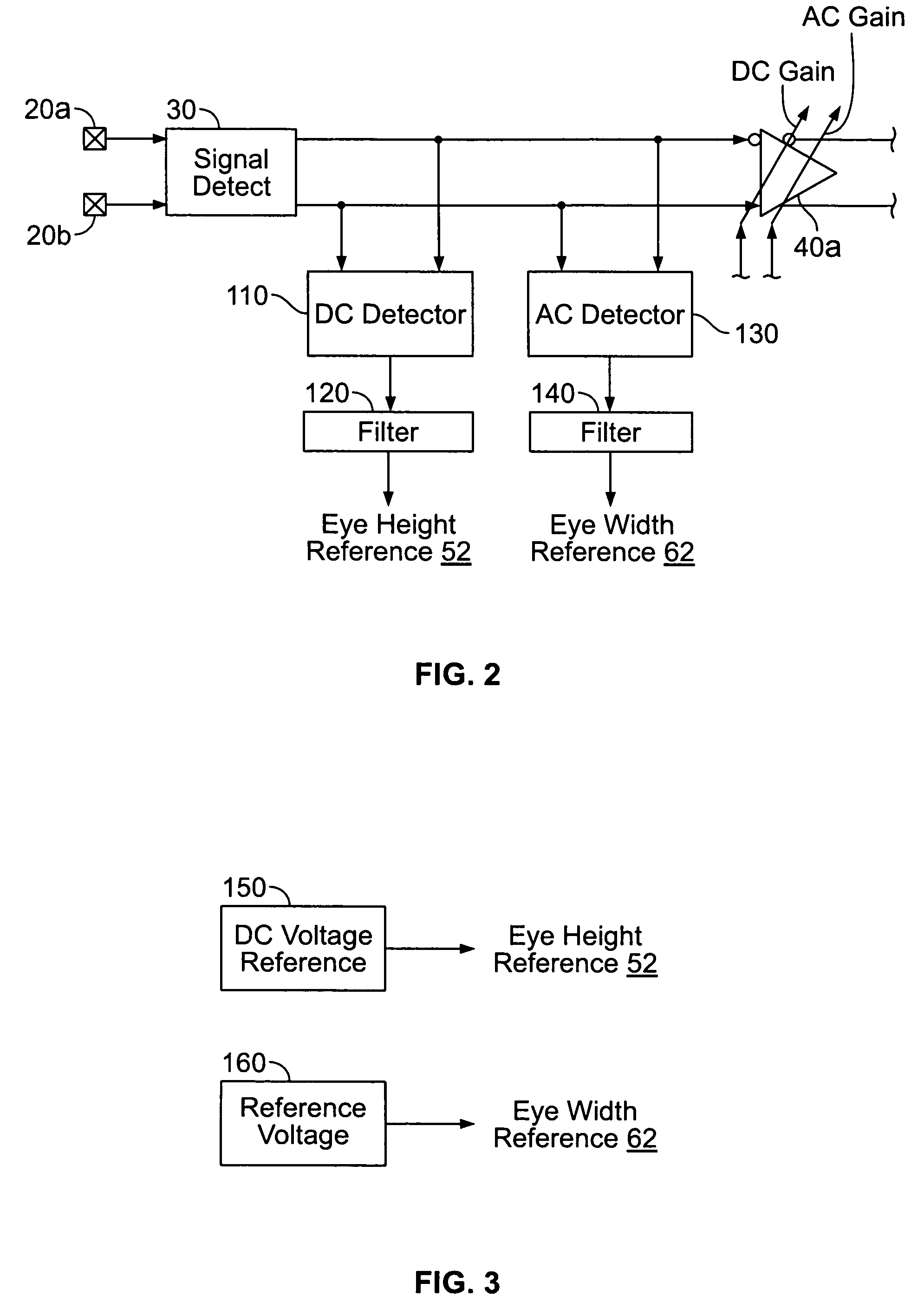
Circuitry for receiving a serial data signal (e.g., a high-speed serial data signal) includes adjustable equalizer circuitry for producing an equalized version of the serial data signal. The equalizer circuitry may include controllably variable DC gain and controllably variable AC gain. The circuitry may further include eye height and eye width monitor circuitry for respectively producing first and second output signals indicative of the height and width of the eye of the equalized version. The first output signal may be used in control of the DC gain of the equalizer circuitry, and the second output signal may be used in control of the AC gain of the equalizer circuitry.

Description

BACKGROUND OF THE INVENTION[0001]This invention relates to high-speed serial interface (“HSSI”) circuitry, and more particularly to automatic calibration of the receiver portion of such circuitry.[0002]High-speed serial data signalling is widely used for transmitting data between devices in electronic systems. As just one example, such signalling may be used to transmit data between several integrated circuit devices on a printed circuit board. Typical high-speed serial data rates are in the range between about 6 Gbps (giga-bits per second) and about 10 Gbps, but higher or lower data rates are also possible.[0003]In many systems that use high-speed serial data signalling, the serial data signal is transmitted without an accompanying clock signal that can be used by the circuitry that receives the data signal to enable the receiver (“RX”) circuitry to know when to sample the received data signal in order to capture successive bits in the received signal. In such cases the RX circuitr...

Claims


Application Information

Patent Timeline
Patent Type & Authority Patents(United States)
IPC IPC(8): H03H7/30H03K5/159H03H7/40
CPCH04L1/205H04L25/03019H04B3/04H04L25/03885
Inventor SHUMARAYEV, SERGEYWONG, WILSON
Owner ALTERA CORP
Learn More